March 5th, 2018
Examples of Progress with Gear Mesh Generator in Unity
The approach for creating a full gear mesh in Unity was to create a single section of a gear with one tooth with the given parameters/dimensions, then replicate this a number of times equal to the total number of gear teeth and rotate each of these instances appropriately to create a single full gear. An extra bit of scripting was added to place small black spheres around the vertices of the first gear segment created, to highlight the locations of the created vertices.
The prior setup was tweaked to account for the control of spaces between the gear teeth. This appears to have made the instances of the meshes concave in some manner though, so the convex mesh colliders do not completely accurately follow the model around the teeth now. Another technique will be looked into to prevent this from happening.
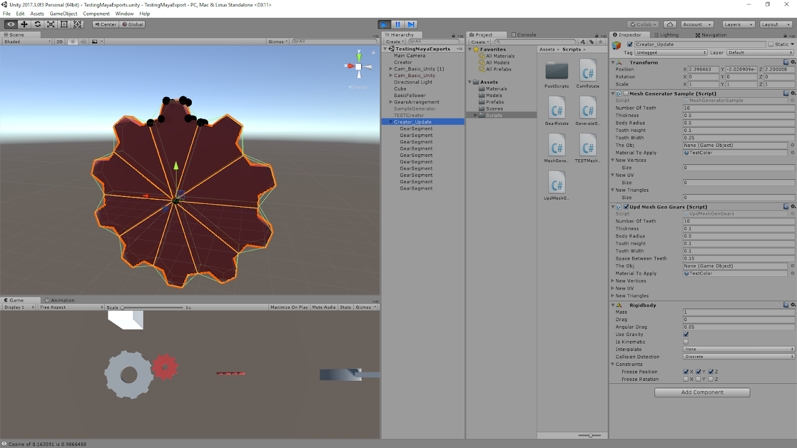
Parameters:
- Number of Teeth: 10
- Thickness: 0.1
- Body Radius: 0.5
- Tooth Height: 0.1
- Tooth Width: 0.1
- Space Between Teeth: 0.15
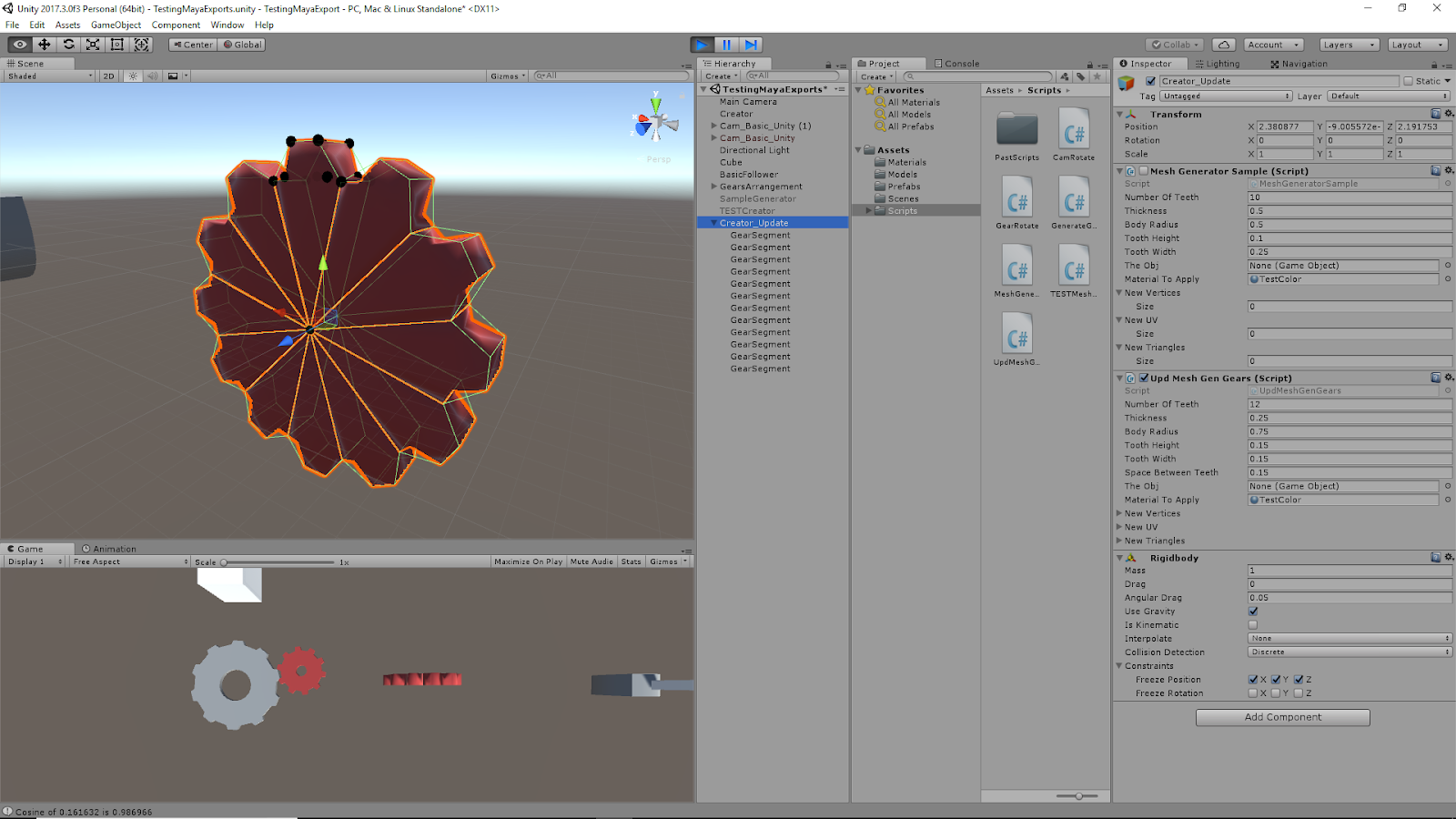
Parameters:
- Number of Teeth: 12
- Thickness: 0.25
- Body Radius: 0.75
- Tooth Height: 0.15
- Tooth Width: 0.15
- Space Between Teeth: 0.15
Video Demonstrations of Gear Generation Script at Work
Shows Physics of Full Gear Mesh
As can be seen from this video, the full gear mesh acts as one object even though it is made of several individual objects each representing a gear segment. It also shows that it has basic physics function within Unity’s game space.
Shows Changing Parameters to Create Different Gear Shapes
This video shows directly how changing the parameters of the script relates to changes of the resulting gear mesh. Currently, all the work is loaded at the start of the scene. Further work will be done to translate this to something that can be edited real time.
Current Equations for Determining Geometry of the Gear Mesh – Shown for Creating Single Gear Section
Parameter Equations
- angleForSpaceBetween = Mathf.Asin(spaceBetweenTeeth / (2 * bodyRadius));
- angleForSpaceBetweenDeg = Mathf.Rad2Deg * angleForSpaceBetween;
- distanceToCenterOfSpace = bodyRadius * Mathf.Cos(angleForSpaceBetween);
- angleBetweenSections = 360 / numberOfTeeth;
- halfAngleBetweenSections = angleBetweenSections * Mathf.PI / 360 – angleForSpaceBetween; // Cuts in half and converts to radians
- cosineTheta = Mathf.Cos(halfAngleBetweenSections);
- sineTheta = Mathf.Sin(halfAngleBetweenSections);
- cosineThetaAlpha = Mathf.Cos(halfAngleBetweenSections + angleForSpaceBetween);
- sineThetaAlpha = Mathf.Sin(halfAngleBetweenSections + angleForSpaceBetween);
Vertex Equations
- newVertices[0] = new Vector3(0, 0, 0);
- newVertices[1] = new Vector3(bodyRadius * sineTheta, bodyRadius * cosineTheta, 0);
- newVertices[2] = new Vector3(-bodyRadius * sineTheta, bodyRadius * cosineTheta, 0);
- newVertices[3] = new Vector3(-toothWidth / 2, bodyRadius * cosineTheta + toothHeight, 0);
- newVertices[4] = new Vector3(toothWidth / 2, bodyRadius * cosineTheta + toothHeight, 0);
- newVertices[5] = new Vector3(0, 0, thickness);
- newVertices[6] = new Vector3(bodyRadius * sineTheta, bodyRadius * cosineTheta, thickness);
- newVertices[7] = new Vector3(-bodyRadius * sineTheta, bodyRadius * cosineTheta, thickness);
- newVertices[8] = new Vector3(-toothWidth / 2, bodyRadius * cosineTheta + toothHeight, thickness);
- newVertices[9] = new Vector3(toothWidth / 2, bodyRadius * cosineTheta + toothHeight, thickness);
- newVertices[10] = new Vector3(distanceToCenterOfSpace * sineThetaAlpha, distanceToCenterOfSpace * cosineThetaAlpha, 0);
- newVertices[11] = new Vector3(-distanceToCenterOfSpace * sineThetaAlpha, distanceToCenterOfSpace * cosineThetaAlpha, 0);
- newVertices[12] = new Vector3(distanceToCenterOfSpace * sineThetaAlpha, distanceToCenterOfSpace * cosineThetaAlpha, thickness);
- newVertices[13] = new Vector3(-distanceToCenterOfSpace * sineThetaAlpha, distanceToCenterOfSpace * cosineThetaAlpha, thickness);