Architecture AI Working with Revit Models and Scripts in Unity

June 15, 2020

Architecture AI Project

Revit Models in Unity

Introduction

We were exploring different methods for importing architectural models into Unity and decided to try Revit to see what it had to offer. The models are easy to move between softwares, and it also creates .cs scripts that Unity can use to provide some interactive data visualization when using the Revit models.

Parameters Import Script

This script creates a large list of strings. It does so by receiving an identification looking string, and uses a method to convert that string into its corresponding parameter information.

Example:

private string ParamByName(string d)
{
switch(d)
{
case “Generic_-_12″_[354721]”:
d = “Area : 8100 ft2 nElevation at Bottom : -1 ft nElevation at Top : 0 ft nType Name : Generic – 12″ n”;
break;


}

return d;
}

Parameter Mouse Over Script

This script uses the name of this.gameObject to add information to the parameter list. The names of all the individual parts of the Revit model correspond to all the input strings found in the ParametersImport partner script. This shows that we most likely need to place this script on every piece of the model individually (since it’s only adding the one name of this.gameObject).

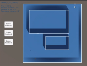
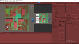
Adding this script to each individual gameObject present in the Revit model got it working. When mousing over the individual parts, it highlights that part with a color and displays some text information about that piece.

Revit In Unity Example

My Example Image of Revit Model with Mouse Over Parameters Shown

The following link shows an example of me using a Revit model in Unity with the corresponding scripts to get the Mouse Over action working.

My Showcase of Revit Model and Scripts

Summary

This is a nice included data visualization tool that can be included essentially for free. The information it provides could possibly be helpful, but the scripts are also very simple so they could easily be tweaked to include other information. All the information is also included in strings within the scripts already, so that data could possibly be extruded for other uses (if that turns out to be an easier way to get said data).

UnityLearn – AI For Beginners – GOAP – Setting Up GOAP System

June 11, 2020

AI For Beginners

Goal Orientated Action Planning (GOAP)

Parts 4, 5, and 6


Beginner Programming: Unity Game Dev Courses

Unity Learn Course – AI For Beginners

Intro

This part of the course gets into actually programming the GOAP system and using it within their example Unity project. These tutorials focused on setting up the foundational classes: GAgent, GAction, GWorld, and WorldStates. These are used as the core of the system as they either hold all the information to pass around through the system, or serve as the base classes to work with for creating agents within the system.

The World States

The World States

    The main scripts created here are:

  • GAgent
  • GAction
  • GWorld
  • WorldStates
WorldStates:

They added another class within this script named WorldState. This WorldState class just holds a string named key, and an int named value. These will be used for a dictionary setup, hence the key and value naming setup. The rest of the WorldStates class itself deals with creating and modifying said dictionary of WorldState objects. It has several dictionary management methods such as: HasState, AddState, ModifyState, RemoveState, SetState, and finally GetStates (to return all states when needed).

GWorld:

This was set as a public sealed class, because this will apparently help with setting up queues in the future. It also makes use of a singleton pattern to create a single location to hold all the world data that can be accessed by many objects.

Actions

Actions

GAction class:

This class is an abstract class, so it will be used as the overall parent class from which all actions for the GOAP system will be derived. Therefore it will serve as a framework for those classes.

Important Fields within this Class:
  • float cost – assigns value to an action (or chain of actions) to help determine between various plans
  • GameObject target – location where action will take place
  • float duration – how long the action will take to perform
  • WorldState[] preconditions – group of preconditions which the action requires to be met in order to perform said action
  • WorldState[] afterEffects – state results from performing this action
  • WorldStates agentBeliefs – states within the agent necessary to monitor with this action

The constructor for the GAction class just initializes a new dictionary for preconditions and effects (preconditionsDict and effectsDict). There is then a method named IsAchievable to determine if a particular goal can be achieved (which just returns true currently and that is it). Then there is an IsAchievableGiven method, which requires an input parameter of a Dictionary of conditions to see if they are present in the preconditionsDict within this action (so it basically returns whether the preconditions of an action are met or not).

Finally, there were two abstract methods added to use in derived actions. These were Preperform() and Postperform(). Preperform provides extra logic to check for before performing an action (i.e. checking what resources or agents are available), and Postperform will hold extra logic for how the world or agent states are impacted after the action is performed.

Agents

Agents

GAgent Class:

This class will use the System.Linq namespace to help sort and organize objects. They also added a SubGoal class within the GAgent script. This helps hold goals within the overall goal that can be added and removed as they are completed. This tutorial sets up the GAgent class so that it can be populated with GAction objects that are available for that specific GAgent.

General Unity Note – GetComponents Method

They use this.GetComponents (plural) to fill an array with all the components located on this game object. That is a good way to quickly populate an array with a bunch of similar components on a single game object I hadn’t used before.

Summary

It was nice to finally get into actually programming the GOAP setup after following all the conceptual work. I really enjoy setting up base classes for bigger systems and getting to see the foundation of the GAction class specifically is interesting and I am excited to see how it ends up working out. I can already start to see how the flexibility of this system works through the GAction class specifically.

It feels like a lot of information needs to be passed around, and there are going to be some large classes holding a lot of information at one time, such as those holding information about the entire world state. I am interested to see how they approach these two issues while keeping everything manageable on the programming side while also keeping it running efficiently enough to run several agents (and different types of agents).

UnityLearn – AI For Beginners – GOAP – Introduction to GOAP

June 10, 2020

AI For Beginners

Goal Orientated Action Planning (GOAP)

Parts 1, 2, and 3


Beginner Programming: Unity Game Dev Courses

Unity Learn Course – AI For Beginners

Intro

This course covers goal orientated action planning (GOAP) as another way to set up flexible systems of AI behavior. This blog covers the first 3 tutorials of the course which introduce the general GOAP concept by defining its parts and explaining the planning process going in to creating a GOAP system.

An Introduction to GOAP

GOAP Introduction

    Goal Orientated Action Planning (GOAP):

  • has all the elements of a finite state machine, but uses them differently
  • uses graphs for processing
  • GOAPs actions and goals are decoupled
  • actions are free elements in the system that are mixed/matched to meet goals
  • instead of having a list of actions needed to meet a goal, GOAP allows for multiple solutions to be chosen from
Actions

Components: Precondition, Effect
Precondition: state that must be met before the action can take place
Effect: how the action leaves the state of the agent (or world) after the action has occurred
Actions are connected similarly to dominoes where the effects of actions are matched with the preconditions of other actions to create action chains.

Goal: the end state of the agent

Creating a plan comes from understanding the current state of the agent itself and the world around it. The planning stage of GOAP works backwards to see if it is achievable from the currents states (again, of the agent and the world it understands). Since this approach can lead to multiple action chains that lead to the same goal, costs are implemented to help the agent decided which action chain to choose (and in the case of a tie, one can be selected at random).

A general GOAP system follows this structure where actions, goals, and the world state data are fed into a planner. The planner chains actions together according to the goals and starting states to see which plans are achievable. The planner uses the A* algorithm (exactly the same as some pathfinding algorithms) to determine the “best plan”. Once a plan is generated, the agent goes to achieve it with a simple state machine. This state machine looks to simply move the agent where it needs to be to perform the actions necessary, and perform said actions until a goal is achieved. Before each action is performed, it is checked to see if it is valid. If it is not valid anymore, the entire plan is abandoned, and a new plan is generated.

One of the biggest benefits of the GOAP approach is that new actions can continually be added to the pool of available actions for the agent. These actions will then always be picked up by the planner as another possible action to create an action chain or plan to solve a goal. The planner effectively creates the total graphs of actions for the designer, so it is also just easier to program additional factors as complete graphs do not need to be directly programmed as is more common with complete finite state machines.

Setting Up A GOAP Environment

Setting Up A GOAP Environment

This first major tutorials starts the setup for a basic GOAP project. It is set in a small hospital with patient agents and nurse agents.

Patient Agents

They come into the hospital and get registered at the recption desk. They then move to the waiting room until it is their time to be received by the hospital where they are then brought to a cubicle to be checked on before leaving the hospital.

Nurse Agents

They operate the reception desk receiving incoming patient agents, they come and grab patients from the waiting room to take them to a cubicle to check on them, and they can also rest in the staffing area if they need a break.

Since a lot of the actions and goals of these two agents are heavily location based, they implemented an underlying waypoint system to the entire setup. Empty gameobjects are set at all the critical locations to be used as waypoints for guiding the agents moving forward. All the waypoints have been tagged with individual unique tags to help the agents locate them immediately upon instantiation.

Pre-Planning the Agent Actions

Pre-Planning the Agent Actions

The foundation of GOAP is that there are: goals, actions, and states. These must all be taken into consideration when planning those which to include and which should be able to lead into others when graphing out plans. An agent has a list of goals it can achieve. It also has a pool of actions it can use to achieve these goals. The actions may also require other actions before being able to be performed. Some actions may also require other agents or some other outside resource.

Patient Actions:
  • Come into hospital
  • Register at the front desk
  • Go to waiting room
  • Get treated when nurse and cubical are available
  • Go home
Nurse Actions:
  • Get Patient
  • Go to Cubicle
  • Rest

The agent must draw information from the world states to help determine what goals are achievable. It will also combine this information with its own state (data it has within itself) to help it determine what is possible. This world state information and the agent state information is passed into the planner, along with all the goal and action options of the agent, so the planner can generate a plan for the agent.

Summary

Overall this felt like a good introduction to the GOAP AI system approach. While I don’t think I could build my own systems quite yet using it, I have a much better understanding of the overall concept and how it can be used to create a flexible set of options for actions for AI’s to use to guide their behavior. The ability to add actions to this pool with relatively little cost is very nice for creating a scalable system with a lot of variability. I could also see this leading to a lot of interesting emergent behavior with large pools of agents, goals, and actions. I look forward to the next parts of the course where they get more into how to program such a system.

Architecture AI Reading CSV File Data to Use in Node Grid

June 8, 2020

Architecture AI Project

Read CSV File

General Goal

For this architecture project we wanted to be able to read data exported from other softwares into Unity. Initially we will be using data from Rhino, but it will be converted to a very generic format (like .csv), so it should be more widely applicable. This data will be used as another way to inform the node system and assign architectural values to these nodes which will again be used to inform the decisions of the agents traveling with the node system.

Using Text Data in Unity

Our text files will be very simplistic, so we can use a very straight forward approach to organizing and using the data from the text files. Each line of data is important for a single node, so splitting on a line will help organize individual node information. Then we just have to split up the information within that line to spread the information out to the proper variables within the node.
Both of these actions can be handled with a string array created from using the Split method at a specific character. Split() is a method within the String class which allows you to easily create separate strings from a single string that is split at a certain location. To create the separate lines of data, the strings are split on the new line character (‘n’), where as when we are splitting up the data within a single line, we split the string on the comma character (‘,’). This specifically works here since we are dealing with .csv files.
This approach pretty easily parsed out the .csv data for me in string format to start using with the node system.

Visualizing Proper .csv Data Distribution on Nodes

I wanted a way to effectively assess and debug whether the system was working properly or not, so I decided to use my node visualization approach I have used for other values already. Using my heat map coloring system for the node visualizer, I just want to visualize the nodes in accordance with their connectivity values (which will be fully applied by the .csv file and the file reader alone).

Actually Applying .csv Data to the Nodes in Grid

This process is much more difficult to find a solution which is quick and somewhat efficient. The original thought of just searching and matching locations blindly would take a very long time every time a grid was initialized, so using the organization of the data to assign these more efficiently will be key.

Approach #1:

Since the .csv data is organized by coordinates in a way similar to how the grid is built in the first place, it made sense to just fill the Node data in from the .csv file data as the grid was built. As long as the .csv data is incremented in a way to continually match the new node positions, this should work rather well.

Issues:

The .csv data is not perfectly rectangular. It does not have values at all for areas where there are gaps or holes, which the node grid does, so it is not just a 1:1 ratio of .csv data points and nodes

Solutions:

  • To keep the data aligned, I am using a check to make sure the current Node having its values assigned matches the coordinates within the current chunk of .csv data looking to be assigned
    • If they match, assign the architectural value (connectivity in testing) and increment the .csv data counter
    • If they do NOT match, do NOT assign the value and do NOT increment the .csv data counter
    • This helps hold on to the .csv data until the proper node is found
    • This must be done very carefully however as if they ever get out of sync, it will basically just stop assigning data forever (because it will just continually wait until the proper node is found)
  • Keeping array indices correct for both sets of arrays is paramount for this system to work
    • The Grid nodes start at 0 and go to (maxDimension – 1)
    • The File nodes start at 1 and go to (maxDimension)
    • The Grid is fully rectangular, where as the File skips coordinates where there is no data
  • Keeping all this in mind, this was the check to keep the arrays straight and assign the proper values to the proper location:
if ((node.gridX + 1) == fullData[dataCounter, 1] && (node.gridY + 1) == fullData[dataCounter, 2])
{
            node.Connectivity = fullData[dataCounter, 3];
            dataCounter++;
        }

    • Just adding 1 to both the x and y dimensions of the grid units makes sure they are in line with the proper data found in the .csv value
    • The dataCounter value keeps track of which row of data to use (which actually ends up reaching the total number of .csv file data nodes (Roughly close to the number of Grid nodes unless there are a lot of gaps))
    • Then the second dimension of the fullData array is simply just the columns of data within the .csv file (so for this basic case, there are only 4 columns)
    • The data from the fullData columns for x and y coordinates are used for the check, then the last column is where the actual value is found that is assigned to the node if the correct one was found
    • The dataCounter is only incremented IF data was actually set
      • This keeps it on the same chunk of data until the proper grid node is found to assign it

Images of Data Visualized

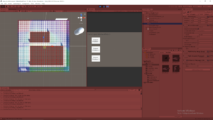
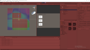
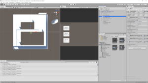
I was able to pass the connectivity data from Rhino into Unity through a .csv file and properly apply that data to the same relative locations within Unity. I overlayed this data with the model that was originally used to generate the data in Rhino, in Unity. I passed the connectivity values into the properly associated nodes as determined by the Rhino .csv value, and then visualized these values on the nodes by coloring them with a heat map-like approach.
I am still using a very basic heat map coloring system that isn’t super clear as the color system I use is cyclical (which means values that are very low and very high both appear reddish), but the images at least show the general idea pretty well. It also shows the gaps are being picked up properly as connectivity values are clearly not assigned there (giving them their base value of 0 which is very low, making those nodes red).

View #1: Node Visualization Over Model

View #2: Node Visualization (without Model)

View #3: Model (without Node Visualization)

Summary / Moving Forward

While this is a good start, it will stay take a lot of work to make the overall system more automated. For example, even this process of keeping the nodes in line with the .csv data is a bit forced because this only works by making the grid have the same dimensions as the .csv data. Further development could help account for cases where you want to scale the system and have more nodes than data points or vice-a-versa.
The models are currently using U.S. units (feet) where as Unity inherently works on the metric system (meters). This immediately presented a bit of a scaling difference just to make sure the data matched up with the actual virtual model. This can make matching everything up exactly a bit tricky because the node system works on an integer system and you can only have whole numbers of nodes, but perfectly matching these systems can result in some fractional values when converting between units, which can end up adding some extra node data around the edges that just isn’t accounted for.

Architecture AI Varied Agent Affinities with Varied Pathing

May 28, 2020

Architecture AI Project

Varied Agent Affinities with Varied Pathing

Demonstration of Varied Agent Affinities with Varied Pathing

Vimeo Link – My Demo of Agents Pathing with Varied Affinities

Explaining Simple but Unclear Heatmap Coloring System

Just to help explain since I don’t have great UI in to explain everything currently, the first thing was that I was testing a really rough “heat map” visual for the architectural values for now. When you turn on the option to show the node gizmos now, instead of uniform black cubes showing all the nodes, the cubes are colored according to the architectural value of the node (for this test case, the window value) Unfortunately this color system isn’t great, especially without a legend, but you can at least see it’s working (I just need to pick a better color gradient). Red is unfortunately both values at/near 0 (min) as well as at/near 100 (max) (but the value range here is only from 0 – 80, so all red in this demo is 0).

Agent Affinity/Architectural Value Interaction for Pathing

The more exciting part is that the basis of the agent affinity and architectural value interactions seem to be working and affecting their pathing in a way that at least makes sense. Again just for demo purposes so far, as can be seen in the video (albeit a bit blurry), I added a quick slider on the inspector for the Spawn Manager to determine the “Window Affinity” for the next agent it spawns (for clarity I also added it as a text UI element that can be seen at the top of the Game View window). Just to rehash, this has a set range between 0 and 100, where 0 means they “hate” windows and avoid them and 100 means they “adore” windows and gravitate towards them.

Test #1: Spawn Position 1

As can be seen in the first quick part of the demo, I spawn 2 agents from the same position 1 but with different affinities. The first has an affinity of 0, and the second has an affinity of 100. Here you can already see the 0 affinity agent steers towards the left side of the large wide obstacle to avoid the blue (relatively high) window area, where as the 100 affinity agent goes around the right side of the same obstacle, preferring the high window valued areas in the blue marked zone.

Test #2: Spawn Position 2

Both the 0 affinity and 100 affinity agents take very similar path, differing by only a couple node deviations here and there. This makes sense as routing around the large high window value area would take a lot of effort, so even the window avoidant agent decides to take the relatively straight forward path over rerouting.

Test #3: Spawn Position 3

This test demonstrated similar results to that of Test #1. The 100 affinity agent moved up and over the large obstacle in the southern part of the area (preferring the high window value area in the middle again), where as the 0 affinity agent moved below the same obstacle and even routed a bit more south just to avoid some of the smaller window afflicted areas as well.

Summary

I did some testing of values in between 0 and 100 and with the low complexity of the area so far, most agents ended up taking one of the same paths as the 0 or 100 affinity agents from what I saw. This will require more testing to see if there already exists some variance, but if not, this suggests that some of the hardcoded behind the scenes values or calculations for additional cost may need tweaked (as is expected). Overall though, the results came out pretty well and seem to make sense. The agents don’t circle around objects in a very odd way, but they also do not go extremely out of there way to avoid areas even when they don’t like them.

Architecture AI Heatmap of Architectural Costs

May 27, 2020

Architecture AI Project

Visualizing Heatmap of Architectural Costs

Architectural Cost Heatmap

I was just using basic black cubes to visualize the grid of nodes in the AGrid A* system originally. Now I finally decided to update that system with a bit more information by adding a colored heatmap to map out the architectural values of the nodes. This will help me understand the pathing of my agents better as they start to use these values in more complex and interesting ways.

Basic Heatmap Color System

It turns out making a heatmap color scale that decently ranges between values of 0.0 and 1.0 is pretty easy. Using HSV color values, you can just vary the H (hue) value while keeping the other two values constant at 1.0 to cover a heatmap spectrum (where H of 0.0 is the lowest value in the range, 1.0 is the highest value in the range, and all other colors are bound within that range). By simply using the min and max architectural values possible in the system as the range bounds I could easily set this type of system up.

Applying Colors to Visualization

For now I decided to just apply this heatmap color methodology to the cubes mapping out the A* grid for now. While these gizmo cubes used to just be colored black for simplicity, now they are colored according to the heatmap color system using the architectural value found within the node.

Bug: Influence Objects Found to Radiate Improperly

The influence objects which apply architectural values to the nodes around them were initially designed to apply in an area around them, with the objects in the center. After applying the heatmap, it was clear that the influence objects were not applying to the nodes intended. It appears the influence actually uses the position of the influence object as the bottom left corner, and radiates upward and to the right (so just in the positive x and z direction away from the object). This is something I will have to look into to make sure it’s an issue with the influence objects, and not the coloring system.

Current Heatmap System (with Bugged Influence Ranges)

UnityLearn – AI For Beginners – Crowd Simulations – Fleeing

May 22, 2020

AI For Beginners

Crowd Simulations

Part 2


Beginner Programming: Unity Game Dev Courses

Unity Learn Course – AI For Beginners

Intro

I was going to combine both of the end parts of the Crowd Simulation tutorial into one blog, but the Flocking tutorial was rather large and interesting so I decided to break it off into its own post. Because of that, this is a smaller one just focused on the basic fleeing crowd logic.

Fleeing

This is similar to the concept covered with single AI agents, it is just being applied to many agents here. An object is introduced to the environment and the fleeing agents determine the vector towards that object, and set a new course for the exact opposite of that vector.

Key Parameters covered for their flee inducing object:
Radius of Influence – how close agents must be to be affected by the object
Cooldown – how long an agent flees before returning to standard behavior

They decided to induce fleeing by adding a cylinder object to the Nav Mesh environment by clicking. This required adding a mouse button script along with adding a dynamic obstacle to the Nav Mesh again (similar to the FPS controller from the last tutorial).

This tutorial gets into several useful NavMesh methods that have not been used yet. These are helpful references to use when expanding and developing my own pathfinding methods, since they show some useful options to give developers when working with intelligent pathfinding.

There are NavMeshPath objects which hold information about a path for the agent to some given destination. You can set these path objects using the CalculatePath method, using a vector3 position (the destination) and the NavMeshPath object as parameters to set that path with that given destination. This alone does NOT set the agent along this path, it simply gets the information for that path (this is useful for the next step).

They perform a check on the path using fields within the NavMeshPath class and an enum named NavMeshPathStatus before actually setting the new destination of the agent. The check is as follows:

NavMeshPath path = new NavMeshPath();
agent.CalculatePath(newGoal, path);

if(path.status != NavMeshPathStatus.PathInvalid){… }

You are able to access the status of a NavMeshPath with a field within the class. They use this to check that the status of the newly created path is valid by checking it against the PathInvalid option within the NavMeshPathStatus enum. Only after passing this check do they set the newly determined path of the agent. Here, they also show that NavMeshPath has a vector3 array field named corners, which are effectively the waypoints of the path the agent uses for its pathfinding.

Summary

This fleeing logic was pretty basic, but it was helpful to learn a bit more about Nav Mesh in general for Unity. The extra information about NavMeshPath was good to learn about, as well as giving me more options on useful aspects to give my own pathfinding systems.

UnityLearn – AI For Beginners – Crowd Simulations – Flocking

May 22, 2020

AI For Beginners

Crowd Simulations

Part 3


Beginner Programming: Unity Game Dev Courses

Unity Learn Course – AI For Beginners

Intro

This was by far the most interesting crowd simulation tutorial covered in the basic AI tutorials. This one really got into an actual rule based logic system for pathing of agents within a large group to move them in an interesting way with emergent behavior that is still controlled and possible to direct.

Flocking

Part 1

Flocking: simple rules to generate movement for groups of individuals to move towards common goals (i.e. birds or fish)

They create a FlockManager because flock movement requires the individual agents to know about and understand they movement and positioning of all the other agents around them. This will be at a higher level providing data for an entire flock as a whole. This starts with logic to instantiate the flock by creating many fish prefabs in a randomized starting position bound around the FlockManager’s position. They also created a class named Flock to go directly on the the individual fish agents themselves.

    Flocking Rules:

  1. Move towards average position of the group
  2. Align with the average heading of the group
  3. Avoid crowding other group members

Flock Rule 1: Move Towards Average Position of Group

This is done by summing all the positions of the agents within the group and dividing by the number of group members, so it directly is the average position of the agents within the group. The agent’s can then find where they are in relation to this average position, and turn towards it.

Flock Rule 2: Align with the Average Heading of the Group

Similar to rule 1, this is also directly an average within the entire group, but this time it is done using the heading vectors of all the agents within the group. The heading vectors are summed and divided by the total number of agents within a group to determine the group’s overall average heading. The agents then attempt to align their heading with this average heading.

Flock Rule 3: Avoid Crowding Other Group Members

The agents must be aware of the positions of their nearest neighbors and turn away from them, as not to collide with them.

Finally, these three rules produce three vectors which are summed to generate the actual new heading of each individual agent.

new heading = group heading + avoid heading + group position

Back in the Flock class, they start applying some of these rules. Here is a list of some of the variables within their ApplyRules() method and what they represent:

Vector3 vcenter = Vector3.zero; // Average center position of a group
Vector3 vavoid = Vector3.zero; // Average avoidance vector (since avoiding all members in group)
float gSpeed = 0.01f; // Global speed of the entire group (Average speed of the group)
float nDistance; // Neighbor distance to check if other agents are close enough to be considered within the same group
int groupSize = 0; // Count how many agents are within a group (smaller part of the group an individual agent considers neighbors)

When setting up their Flock class and applying these rules, they decided to only apply these rules to neighbor agents. This means that the agents are not directly tied to the entire flock at all times, they simply check for agents within a certain distance around them and they only determine their behavior based on all the agents within that certain radius. I just wanted to clarify since it was unclear if some or all of the rules applied to neighbors or the entire flock (here they just apply all rules to only neighbors).

The summary of the Flock class ending here, specifically within the ApplyRules() method, is that each agent finds all the other agents within the given neighbor distance to determine which agents to momentarily flock with. It sums all the positions of these agents together to eventually get the average position. It then checks if these agents are extraordinarily close to determine if it should avoid them, and if so, calculates the avoidance vector (just the vector directly away from that agent) and sums that into a total avoidance vector (which is NOT averaged later on). It then sums all the speeds of the neighbors, again to average later on.

Finally, it checks if the agent is within a group (so is groupSize > 0), and performs the averaging mentioned earlier here. The new heading is calculated here by summing the average center position of a group with the avoidance vector (and subtracting the agent’s position itself to get a proper vector relative to its current position) and the agent performs a slerp to move towards this new heading.

This created a swirling ball of fish that did not particularly seem to deviate from this large mass with a large number of fish (50) and average values for all the sliders (speeds of 0.25 to 2.5; neighbor distance of ~5; rotation speed ~3.5). While moving, significantly reducing the neighbor distance ( < 1.0) did have them separate into smaller groups and swim off infinitely.

Part 2

Adding General Goal Position for Flock

To help provide the group of agents with a general direction, they added a general goal position to the FlockManager class. The Flock class then uses this position within its average center position calculation to help influence the direction of the agents towards this goal position. Initially they tied this to the position of the FlockManager object itself, and moving this around in the editor moves all the agents tied to it in the general direction towards this object (their goal position).

To automate this process a bit, they have the goal position move randomly every now and then within the given instantiation limits (these are the position ranges which the initial agents spawn in around the FlockManager object). This allows for the agents to move around with some more guidance on their own.

They then extend this random “every now and then” process to the Flock class as well. Here they apply it to randomize the agent’s speed and only run the ApplyRules() method occasionally, so they are not constantly following the flocking rules every single frame. This has the added benefit of reducing the processing intensity as well as the agents will not perform the entire logic of flocking every single frame now.

Returning Stray Agents Back to Flock

They finally add logic to deal with rogue agents that leave the flock and travel outward forever. They use the same bounds which determines the general area to spawn all the agents to determine the greater bounds to contain the agents. The Bounds class within Unity is used to check if the agent is contained within these bounds or not. If not, the agent changes its heading towards the FlockManager’s location instead, which remains intact until it encounters other agents to flock with.

Part 3

Obstacle Detection/Avoidance

The major addition in this final flocking tutorial is the addition of obstacle detection. To accomplish this, they have the individual agents cast a physics ray forward, along their direction of travel, and if it detects an obstacle, it will start to turn they away from it.

To have the agents turn away from an obstacle, they choose to use Unity’s reflect method. Using the hit information of the raycast and the normal information from the object hit, Unity can determiner the reflection vector based on the incoming ray. This produces a vector away from an object at the same angle relative to the normal of the surface as the incoming vector.

Video of the Flocking Result In Action

My Flocking Example

Summary

The implementation and fine tuning of Reynold’s Flocking Rules here was by far the most interesting part of the crowd simulation tutorials in this overall section. The idea of using a set of fairly simple rules on many, many agents in a large group to provide interesting yet realistic motion with controllable direction and emergent behaviors is exactly what I hoped for when looking into crowd behavior, and AI in general.

It was interesting to learn that Reynold’s rules are applied to motion by simply converting each of the three rules into their own vector, and then just summing those vectors for the most part. It is also very cool to see just how much you can change up the behavior and general motion of the agents by altering just a few values, like neighbor distance, speed, and rotation speed.

The additional features they covered after the bare minimum of flocking were also very helpful and practical. Showing ways to control stray agents and move them in a unified general direction towards a common goal are very good additional beahviors to add to flocking, and they were implemented in a very easy to understand way. Obstacle detection is also extremely nice, but its implementation was very straight forward and basic so it wasn’t quite as exciting (although the use of the Unity Reflection method is something I hadn’t used before, so that was helpful to learn).

UnityLearn – AI For Beginners – Crowd Simulations – Moving As One & Creating A City Crowd

May 20, 2020

AI For Beginners

Crowd Simulations

Part 1


Beginner Programming: Unity Game Dev Courses

Unity Learn Course – AI For Beginners

Intro

This is the first part of the Crowd Simulations section of the AI course that I covered. This was the first two major tutorials of four, Moving As One & Creating a City Crowd. These introduce the basic concepts of crowd simulations, and at least cover ways to start moving groups of agents with Nav Mesh Agents in Unity to help visualize these concepts (more so than particularly creating agent crowd AI behaviors yourself).

1: Moving As One

Crowd Behavior: agents move enmasse, as opposed to solely as individual units; their movements are usually also dependent on each other’s movements

Reynold’s Flocking Algorithm:

    Common flocking logic based on 3 simple rules:

  1. Turn towards average heading of group
  2. Turn towards average center of the group
  3. Avoid those around you

They start with a really basic Nav Mesh setup with a bunch of blue capsule agents on one side of a tight corridor, and a bunch of red capsule agents on the other side, and they each need to navigate to a goal on the opposite side, running through/past each group of capsules. The standard Nav Mesh Agent setups with colliders gives interesting group interactions by themselves already to start. This simulation was mostly to help visualize the idea of lines of flow in crowds, as well as instances of turbulence within crowd simulations.

2: Creating A City Crowd

Part 1

Starting setup is adding Street Crowd Simulation package to a Unity project. They included a starting scene of a street with several different characters with basic idle, walk, and run animations. This setup just helps visualize crowd behavior in a more interesting and realistic setting. Initially the agents select a random object from all the objects tagged “goal” as their destination and move there.

The additions done in the tutorial were having the agents continue finding new destinations after reaching the first one and adding more static meshes as obstacles for the agents to move around. The first goal used a distance check for once the agents were close enough to their destination, and then they would select another goal randomly from the initialized goal array. To accomplish the second part, they just added large cubes to simulate buildings to make a more realistic street walking setup with the characters.

Part 2

They added a bunch of buildings to the center of the street scene so agents would walk around the outter edge as normal street traffic.

Alternating Character Animations:

All the characters are using the same animations, so they look strange because they are all doing the exact same animations on the exact same time cycles. To rectify this, they looked into the “Cycle Offset” parameter within the standard walking animation for all the characters in the Animator.

They suggest setting this value with the SetFloat method within Unity’s Animator class. I tried doing this to set the value for the float parameter they added and tied to Cycle Offset, but it was not working for me. The string I entered matches the parameter name, and I connected the value to the parameter as they showed, but it was having no effect for me.

FIXED:

I was able to rectify this issue by explicitly stating within the Random.Range method setting the values to use floats for 0 and 1 (with 0.0f, and 1.0f). Without this explicit declaration, it must’ve been using ints and it was only setting everything to 0 every time (so initializing it as it was originally). Making them floats fixed the issue and they were being put on different cycles as expected.

They also set varied starting speeds for the agents. This included changing the speed of their animations along with their actual Nav Mesh Agent travel speed. To keep these working together well, they just randomly selected a float value and applied this same value to both of these parameters.

Dynamic Nav Mesh Obstacle (with First Person Controller):

They then move on to adding dynamic Nav Mesh obstacles by adding a First Person controller and making the player an obstacle on the Nav Mesh. This is done simply by adding a Nav Mesh Obstacle to the First Person controller. It creates a wireframe similar to a collider that can be shaped and controlled to control the area it removes from the Nav Mesh itself.

Summary

Overall the tutorials have been extremely basic so far and have not really delved into the actual AI behaviours of groups yet really. I am hoping they explore implementing Reynold’s Flocking theorem at some point so I can get some experience with that. If not I may take a detour into the world of “boids” to expose myself to more crowd behavior AIs.

UnityLearn – AI For Beginners – Autonomously Moving Agents

May 13, 2020

AI For Beginners

Autonomously Moving Agents

*Full Course*


Beginner Programming: Unity Game Dev Courses

Unity Learn Course – AI For Beginners

Intro

I completed the full course for Autonomously Moving Agents within the AI Unity Learn course and am just covering it all in this blog post. I broke each individual tutorial into its own section.

1: Seek and Flee

They start a new project and scene with this project where there is a robber (NPC) and a cop (player controlled), and the robber will be given logic to satisfy seeking and fleeing in relation to the player and the terrain obstacles.

Seek: Follow something else around
Flee: Move away from a specific object

Seek follows logic they have already used for following an object. Using the difference in positions between two objects, you can generate a vector which gives the direction between them and use that to guide an object towards the other one. Similar logic is actually used for Flee, except they just use the opposite of the vector generated between the objects to inform the agent of a direction directly away from a specific target. Since most movement done currently in these projects is target based, they just add the agent’s position to this vector to actually create a target to use in the desired direction.

2: Pursuit

Pursuit: similar to seek, but uses information to determine where the target will be to decide on pathing, as opposed to just its immediate location

Mathematically, this uses information on the target’s position, as well as it’s velocity vector to determine the target location. This information combined with the npc’s information on its own speed allow it to determine a path which should allow it to intercept its target some time in the future assuming a constant velocity.

Conditions they are adding for varied movement: If player is not moving, change NPC behavior from Pursue to Seek If NPC is ahead of player, turn around and change Pursue to Seek

They again use the angle of the forward vectors and vectors between the two interacting objects to determine the relative positioning of the NPC and player (whether the NPC is ahead of the player). They use a Transform method, TransformVector, to ensure the target’s forward vector is accurately translated to world space to compare with the NPC’s own forward vector in world space to get a proper angle measurement.

3: Evade

Evade: similar to pursuit but uses predicted position to move away from where target is predicted to end up

Since it is so similar to pursuit, implementing it in the tutorial could basically be done by copying the pursuit logic and just changing the Seek method to the Flee method (which effectively just sets the destination to the opposite of the vector between the agent and its target position). They do it even more simply by just getting the target’s predicted position and straight away using the Flee method on that position.

4: Wander

Wander: it is the somewhat random movement of the agent when it does not have a particular task; comparable to the idle state of standing

Their approach for wander is creating a circle in front of the agent where a target location is located on the edge of this circle and moves a bit along the circle to provide a bit of variety in the agent’s pathing

Important Parameters: Wander Distance: distance from agent to center of circle Wander Radius: size of circle Wander Jitter: influences how target location moves about circle

5: Hide

Part 1

Hiding requires having objects to hide behind. Their approach is to create a vector from the chasing object to an object to hide behind, and extend this vector a bit to create a target destination for the agent to hide at. A vector is then created between the hiding agent and this hiding destination to guide pathing.

The “hide” objects are tagged “hide” in Unity, and are static navigational meshes. They created a singleton class named World. This would hold all the hide locations. This does this by using the FindGameObjectsWithTag method to find all the objects with the “hide” tag.

They mention two ways to find the best hiding spot. The agent can look for either the furthest spot or the nearest spot. They decided to use the nearest spot approach.

Hide Method

Goes through the array of all the “hide” tag objects gotten in the World class and determines the hiding position for each of them relative to the target object it is hiding from. Using this information, it chooses the nearest hiding position and moves there. The hiding position is determined by creating a vector between the target the agent is hiding from and every hide object, and starting from this point, it adds a bit more in the same direction so that it is some distance behind the hiding object and the hiding object is between the target and the agent.

Part 2

The hide vector calculations use the transform position of the hiding objects, which is in the center of the object generally. This means setting the agent some distance away from the center should vary because objects can be different sizes.

To consistently get a position close to an object regardless of its size, they use an approach where the objects have a collider and the vector passes fully through this collider and beyond. It then produces a vector from that position coming directly back in the opposite direction until it hits the collider again. This position where it hits the collider is then what is used as the position for the agent to hide in. This is done because it is much easier to determine where a ray or vector first collides with a collider than where it leaves a collider.

The new method they created with this additional logic is named CleverHide(). Combining this logic with the NavMeshAgent tools in Unity can require some fine tuning. The main factor to keep track of on the NavMesh side is the stopping distance, as this is the distance the agent has to get within the actual destination to be good enough for the system to stop the agent.

They added a house object to test the system with more objects of various sizes and it worked ok. It was interesting because the agent wouldn’t move with significant moving from the target player, so sometimes you could get very close before it would move to another hiding position. I am not positive if this was another NavMesh stopping distance interaction or something with the new hiding method.

Finally, for efficiency purposes they did not want to run any Hide method every frame so they looked to add a bool check to see if the agent was already hidden or not before actually performing the Hide logic. To check if the agent should hide, they performed a raycast to see if it could directly see the player target. If so, it would hide, if not, it would stay where it was at.

6: Complex Behaviors

Complex Behaviours: combining the basic behaviours covered so far to give decisions for the agent to determine how it should act. The first combination they do is choosing between pursue (when player target is looking away) and hide (when player target is looking at them). The looking check is done with an angle check between the target and the forward vector.

They also added a cooldown timer to update the transition between states since it led to some very weird behavior when hiding with the current setup (the agent would break line of sight with the target immediately upon hiding, which would then cause it to pursue immediately, and then hide again, etc. so it would just move back and forth at the edge of a hiding spot).

7: Behavior Challenge

Challenge: Keep pursuit and hiding as they are Include range If player is outside distance of 10, agent should wander

My approach: I added a bool method named FarFromTarget() that did a distance check between the agent and the target. If the magnitude of that vector was greater than 10, it returned true, otherwise it returned false.

Then in Update I added another option of logic after the cooldown bool check to see if FarFromTarget was true. If so, the agent entered Wander and else it performed the similar logic before with the checks to perform either CleverHide or Pursue.

Their approach: They also created a bool method, but they named it TargetInRange(). Following this, they did the same exact process I did. They checked for TargetInRange within the cooldown if statement check, and performed Wander above all else, then it checked with else if it did the other previous logic (CleverHide or Pursue).

Summary

All these behaviors are actually relatively simple on their own, but as shown in the final tutorials, combining these with transitions can create interesting and seemingly complex behaviors. This type of design would work very well with the Finite State Machine systems covered in earlier tutorials (as well as others I’ve researched as well). State Machines are also very nice to ensure the isolation and encapsulation of the individual types of behavior.