Architecture AI Pathing Project: Fixing Highlight Selection Bugs

March 22, 2021

Highlight Selection

Architecture AI Project


Overview

I was having a bug come up with our selection highlight effect where sometimes when moving around quickly, several objects could be highlighted at the same time. This is not intended, as there should ever only be a single object highlighted at once, and it should be the object the user is currently hovering over with the mouse.

Bugfix

Assessing Bug Case

Since it happened generally with moving around quickly in most cases, it was difficult to nail down the direct cause at first. After testing a while though, it was noticeable that the bug seemed to occur more often when running over an object that was non-selectable, onto a selectable object. Further testing showed this was the case when directly moving from a non-selectable to a selectable object right afterward. This helped isolate where the problem may be.

Solution

It turns out in my highlight selection SelectionManager class, I was only unhighlighting an object if the ray did not hit anything or it did both: 1) hit an object and 2) that object had a Selectable component. I was however not unhighlighting an object if the ray: 1) hit an object and 2) that object did NOT have a Selectable component. This logic matched up with the bug cases I was seeing, so this was the area I focused on fixing.

It turns out that was where the error was coming in. By adding an additional catch for this case to also unhighlight an object when moving directly from a selectable object to a non-selectable and back to a selectable object again, the bug was fixed.

Architecture AI Project: Fixing Selection Highlight Bug from Steve Lilley on Vimeo.

Summary

This was a case of just making sure you are properly exiting states of your system given all cases where you want to exit. This could probably use a very small and simple state machine setup, but it seemed like overkill for this part of the project. It may be worth moving towards that type of solution if it gets any more complex however.

via Blogger http://stevelilleyschool.blogspot.com/2021/03/architecture-ai-pathing-project-fixing_22.html

Architecture AI Pathing Project: Cleaning Build UI

March 15, 2021

Working with UI

Architecture AI Project


Working with UI

Since UI looked organized into 4 major groups vertically, I used a Vertical Layout Group for the overall control. I then filled this with 4 empty UI objects, one for each major UI group.

Vertical Layout Group

  • Anchor Preset: stretch/left (anchors to the left, but expands for full vertical screen space)
  • Pivot: (0, 0.5) (Moves pivot point to the far left, so width controls how much it expands out from edge, and Pos X can just remain 0)
  • Child Force Expand: Width (Helps expand everything to fit the full width)
  • Child Force Expand: Height (May not be needed)
  • Control Child Size: Width (May not be needed)
  • Padding: Left, Top, Bottom (Keep everything slightly away from edge)

Controlling the anchors and pivot is extremely important. After setting up the vertical layout group, a lot of the individual control is necessary for the horizontal organization. The anchors, the x position in particular, can be used to help stretch the UI objects to fit whatever is dictated by the overall layout group container.

Using Anchors

For example, many objects are side by side and want to fit half of the given width. To do this, the left object uses anchor X values of min = 0.0 and max = 0.5. The right object uses X values of min = 0.5 and max = 1.0. The values are percentage based, so this allocates the first half of the given space to the first object and the second half to the other.

Using Pivots

The pivot then ties in as this is the base point, or handle of the UI object, so this is the point that all the positioning is relative to. So many of the objects start with a pivot at (0.5, 0.5), which is in the center of the object. This requires annoying extra positioning values, normally half of the width of the object, to fit properly. By moving the pivots though, they become much easier to position.

Again, looking at the UI examples that have 2 objects split the space horizontally, the pivots are used somewhat similarly to the anchors. The left object has its pivot set to (0, 0.5), so the X is set to 0.0. The right object has its pivot set to (1.0, 0.5), so the X is set to 1.0. These are again percentage based, so the (0, 0.5) pivot moves the handle to the extreme left of the object, and the (1.0, 0.5) moves the pivot to the extreme right. This way, the “X position” (now named Left and Right) can just be set to 0. This is conjunction with the edited anchor points will position the object perfectly to fill half the space horizontally.

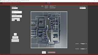
These uses of UI anchor and pivots can be seen in the following figure in the bottom two groups of UI elements as I worked through applying them (the section with the “Run Sim” button and the section with the “Output .csv” button). The upper sections had not been modified yet.


Fig. 1: Example of These UI Modifications in During Work in Progress (Only Lower 2 Sections)

Summary

I learned a lot about the workings of UI elements in Unity by getting this setup much more organized. The anchors help locate the extents of the positions of a UI element, where as the pivot is simply the base point all the positioning and scaling originates. I also found that changing the anchor presets just has a set value for this different options (which completely makes sense once you look at it). For instance, stretch just sets the anchors to 0.0 and 1.0 to force it to fit the area it is parented by (or the entire screen).

via Blogger http://stevelilleyschool.blogspot.com/2021/03/architecture-ai-pathing-project.html

Architecture AI Pathing Project: Fixing Weird Build Bugs

March 11, 2021

Build Issues

Architecture AI Project


Overview

After working on the project with a focus on using it in Editor for a while, we finally decided to try and see if we could build the project and work with it from there. Initially it did not provide anything useable. It would build, but nothing could be done. After a while, I isolated that the colliders were giving trouble so I manually added them for a time and that helped set up the base node grid. The file reader however was unable to provide data to the node grid, so only one aspect of applying data to the pathing node grid worked.

These issues made the build fairly unuseable, but provided some aspects to approach modifying in order to fix the build. After some work focusing on the issue with applying colliders and reading/writing files, I was able to get the builds into a decently workable spot with hope to get the full project useable in a build soon!

Unable to Apply Colliders with Script: Working with Mesh Colliders at Run Time

This first issue right off the start of opening the build was that my script for applying mesh colliders to all aspects of the model of interest was not working. This made sense as a cause for the node grid not existing as raycasts need something to hit to send data to the node grid. Further testing with simply dropping a ball in the builds showed it passed right through, clearly indicating no colliders were added.

I used a band aid fix temporarily by manually adding all the colliders before building just to see how much this fixed. This allowed the basic node grids to work properly again (the walkable and influence based checks). The daylighting (data from the file reader) was not working still however, which showed another issue, but it was a step in the right direction.

Solution

With some digging, I found that imported meshes in Unity have a “Read/Write Enabled” check that appears to initially be set to false on import. While this does not seem to have an effect when working in the editor, even in the game scene, this does seem to apply in a build. So without this checked, the meshes apparently lose some editing capabilities at run time, which prevented the colliders from being added by script. Upon checking this, adding the colliders worked as intended.

File Reader Not Working: Differences Between Reading and Writing Text Files in Unity, and the Difficulties of Writing

While this got the build up and working at least, we were still missing a lot of options with the node grid not being able to read in data from the File Reader. Initially I thought that maybe the files being read were just non-existent or packaged incorrectly so I checked that first. I was loading the files in through Unity’s Resources.Load() with the files in the Resources folder, so I thought they were safe, but I still needed to check. To do so I just added a displayed UI text that read out the name of the file loaded if found, and read out an error if not found. This continuously provided the name of the file, indicating it was being found and that may not be the problem.

Difference Between “Build” and “Build and Run” in Unity

I was doing all my testing by building the project, and then finding the .exe and running it myself. Eventually I tried “Build and Run” just to test a bit faster, and to my surprised, the project totally worked! The File Reader was now working as intended and the extra pathing type was being read in properly and applied to the underlying node grid! But this was not a true solution.

To double check, I closed the application and tried to open it again directly from the .exe. Once I did, I found that again, the project was NOT applying the data properly and the file reader was NOT working as intended. This is important to note as “Build and Run” may give false positives for your builds working, when they actually don’t when run properly.

I found an attempt at an explanation here when looking for what caused this, as I hoped it would also help me find a solution:


Unity Forums – Differences between Build – Build&Run?


One user suggests some assets read from the Assets folder within Unity’s editor may still be in memory when doing “Build and Run”, which is not the case when simply doing a build. Further research would be needed though to clarify what causes this issue.

Solution

This did not directly lead me to my solution, but it did get me looking at Unity’s development builds and the player.log to try and find what issues were being created during the running of the build. This showed me that one part of the system was having trouble writing out my debug logs that were still carrying over into the build.

Since these were not important when running the build, I just tested commenting them out. This actually fixed the process and the File Reader was able to progress as expected! This read the file in at run time, and applied the extra architectural data to the pathing node grid as intended!

Reading vs. Writing Files through Unity

This showed me some differences in reading and writing files through Unity, and how writing requires a bit more work in many cases. Unity’s build in Resources.Load() works plenty fine as a quick and dirty way to read files in, even in the building process as I have seen. Writing out files however requires much more finesses, especially if you are doing something with direct path names.

Writing out files pretty much requires .NET methods as opposed to built in Unity methods, and as such might not work as quickly and cleanly as you hope without some work. When done improperly, as I had setup initially, it directly causes errors and stops in your application when you finally build it as the references will be different from when they were running in the Unity editor. This is something I will need to explore more as we do have another aspect of the project that does need to write out files.

Summary

If you want to modify meshes in your builds and you run into issues, just make sure to check if the mesh has “Read/Write Enabled” checked. Reading files with Unity works consistently when using a Resources.Load() approach, but writing out files is much trickier. Finally, use the dev build and player.log file when building a project to help with debugging at that stage.

via Blogger http://stevelilleyschool.blogspot.com/2021/03/architecture-ai-pathing-project-fixing.html

Drawing and Rendering Many Cube Meshes in Unity

March 02, 2021

Drawing and Rendering Meshes

Unity


Title:
Drawing 1 Million cubes!


Unity – Forum

Description:
Discussions and code for drawing and rendering many cube meshes.


Overview

I wanted to be able to replicate the drawcube Gizmos in Unity I am using to portray data for my architecture project in the game scene and eventually builds of the project. To do this I need a very lightweight way to draw many small cube meshes, so I looked into drawing/rendering my own meshes and shaders. This option I came across in a Unity forum to just draw and render meshes on Update seemed decent enough so I investigated a simpler version for my needs.

Implementation

I could get away with a much simpler version of the CubeDrawer script found in the forum comments. I could strip out the batching and the randomization as I need very specific cubes and no where near the million cubes they were rendering. I am normally looking at somewhere in the thousands to ten-thousands, and want very specific locations.

So I stripped this script down and tweaked it some for my needs so I could feed the position and color data I was already creating from my node grids and heatmaps into this simpler CubeDrawer. I then had it build and render the cubes. It was able to give me the visual results I wanted, but I was seeing a significant performance reduction. The AI agents had stuttery movement and the camera control had a bit of lag to it. I’ll need to investigate ways to reduce the performance hit this has, but it’s a step in the right direction.

via Blogger http://stevelilleyschool.blogspot.com/2021/03/drawing-and-rendering-many-cube-meshes.html

Architecture AI Pathing Project: Rename Dropdown Elements

February 16, 2021

Dropdown and Input Field UI

Architecture AI Project


Renaming Items in Spawn/Target Dropdown Lists

To get the spawn/target object lists into the dropdowns quickly and accurately, I had them simply add their gameobject names to the dropdowns for the individual item names. These objects however tend to have very long names as they are constructed from several elements coming from the Revit system to accurately identify them. While useful, they are too wordy for identification purposes here and can actually make them harder to find and keep track of. Because of this, we wanted to investigate a way to rename the elements in the list to make them easier to identify in the future.

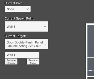
To accomplish this I looked to add a UI Input Field where any name could be entered and this could be used to rename current items in the dropdown lists. Since there are two dropdowns (Spawn list and Target list), I added two different buttons to account for these. One button applies the current Input Field string as the name of the currently selected Spawn dropdown item, the other button applies it to the Target dropdown item.

The following images help show the name changer in action. The crucical elements are located in the top/central left.

Fig. 1: Initial Setup with Newly Included Input Field and Name Changing Buttons


Fig. 2: Effect of Adding Text to Input Field and Selecting the ‘Rename Spawn’ Button

Clean Up and Error Reduction

Restricting Controls when Accessing Input Field

I added some camera controls to help get around the environment, which included some keyboard shortcuts. These shortcuts however would activate while typing within the Input Field initially. I wanted to disable the camera controller while in the Input Field, so I found Unity has an easy way to determine if a UI element is currently focused, which can be used as a bool to dictate controls. This check can be done with the following:


EventSystem.current.currentSelectedGameObject


So I added a check that if this is null, allow the camera controller inputs, otherwise, disable them.

Null Input Field Check and Instant Dropdown Item Refresh

To keep the dropdown from getting too confusing and adding weird blank items, I added a check to make sure the Input Field is not null or empty before allowing the buttons to edit the current dropdown names. I also found initially that the dropdown item name would change in the dropdown, but it would not be reflected in the current dropdown selections. This looke awkward as I am always updating the current selection, so it would not actually be reflected until you selected the item from the dropdown again. To fix this, Unity’s dropdowns have their own method called RefreshShownValue(), which perfectly resolved this situation.

via Blogger http://stevelilleyschool.blogspot.com/2021/02/architecture-ai-pathing-project-rename.html

Architecture AI Pathing Project: Upward Raycast for Better Opening Detection

January 11, 2021

Raycast for A* Nodes

Architecture AI Project


Original Downward Raycast and Downfalls

The raycasting system for detecting the environment to setup the base A* pathing nodes was originally using downward raycasts. These rays traveled until they hit the environment, and then set the position of the node as well as whether it is walkable or not. An extra sphere collision check around the point of contact was also conducted so as to check for obstacles right next to the node as well.

This works for rather open environments, but this had a major downside for our particular needs as it failed to detect openings with in walls and primarily doors. Doors are almost always found within a wall, so the raycast system would hit the wall above the door and read as unwalkable. This would leave most doors as unwalkable areas because of the walls above and around them.

Upward Raycast System Approach

Method

The idea of using an upward raycast was that it would help alleviate this issue of making openings within walls unwalkable when they should be walkable. By firing the rays upward, the first object hit in most cases can safely be assumed to be the floor because our system only works with a single level at this time. Upon hitting the first walkable target (in this case, the assumed floor), this point is set and another raycast is fired upward until it hits an unwalkable target. If no target is hit, this is determined as walkable (as there is clearly nothing unwalkable blocking the way), but if a target is hit, the distance between these two contact points is calculated. This distance is then compared with a constant height check and if the distance is greater, the node is still marked as walkable even though it eventually hit an unwalkable object.

This approach attempts to measure the available space between the floor and any unwalkable objects above it. If a wall is set directly onto the floor, as many are, the distance will be very small so it will not meet the conditions and will be set unwalkable appropriately. If there is a walkable door or just a large opening such as an arch, the distance between the floor and the wall above the door or the example arch way should be large enough that the system notes this area is still walkable.

Sphere Collision Check for Obstacles

Similarly to the original system, we still wanted a sphere collision check to help note obstacles very close to nodes so that the obstacles would not slip between the cracks of the rays cast, effectively becoming walkable. We included this similarly, but it is noted because the initial hit used is now below the floor, so the thickness of the floor must be accounted for. Currently a larger radius check is just needed so it can reach above and through the floor. In future edits, it could make sense to have a noted constant floor thickness and perform the sphere radius check above the initial raycast contact point according to this thickness.

Test Results

Details

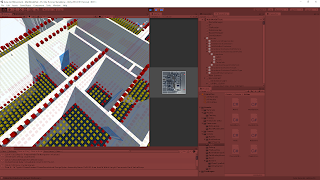
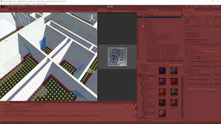
I compared the two raycast methods with a few areas in our current test project. In the following images, the nodes are visualized with Unity’s cube gizmos. The yellow nodes are “walkable” and the red nodes are “unwalkable”. Most of the large white objects are walls, and the highlighted light blue material objects are the doors being observed.

Test 1

A high density door area was chosen to observe the node results of both systems.

The downward check can work for doors when the ray does not directly hit a wall, as the sphere check properly checks them as walkable from the floor. However, the rays hitting the walls can be seen by the unwalkable nodes placed on top of them. A clear barrier is formed along the entirety of the walls, effectively making the doors unwalkable.

The upwards raycast test clearly shows every door has at least a single node width gap of walkable nodes in every case. The doors that were originally unwalkable with the downward raycast and now walkable as the height check was met.

Test 1: Downward Raycast


Test 1: Upward Raycast

Test 2

A larger room with a single noteable door was observed.

The downward check does pose a problem here as a full line of unwalkable nodes can be seen on the floor blocking access through the door and into the room. Because the problem is seen with nodes on the floor rather than nodes on top of the wall, this is actually a case where the sphere collision check is the problem and not the raycast particularly. Changing the collision radius for the check could potentially solve the issue here.

The upwards raycast is able to cleanly present a walkable path through this door into the room. While this does give us the result we desired, it should be noted again this difference can be attributed to the difference in the sphere collision check for obstacles. The same radius was used for both tests, but the upwards raycast sphere orginates from the bottom of the floor, so the extra distance it has to travel through the floor is what really opens up this path.

Test 2: Downward Raycast


Test 2: Upward Raycast

Summary

The upwards raycast seems extremely promising in providing the results we wanted for openings, doors especially. The tests clearly demonstrate that it helps with a major issue case the downward check had, so it is at worst a significant upgrade to the original approach. The upward raycast with distance check method also succeeded in other door locations, supporting its consistency. It will still have trouble from time to time with very narrow openings, but should work in a majority of cases.

via Blogger http://stevelilleyschool.blogspot.com/2021/01/architecture-ai-pathing-project-upward.html

Architecture AI Pathing Project: Revit Data Applying Helper Class

December 9, 2020

File Reader

Architecture AI Project


Enhancing the Extendability of the Revit Parameter Data Application Class through Helper Class

I got the basics of reading in a specified set of parameter data from Revit to apply to the model in Unity, but we would need to have options for possibly using many sets of data from there. To handle this I wanted to make it easy to add ways to handle all the differents types of logic with these sets of data. This started by creating a foundational interface that any class utilizing the data would implement, but I also needed a way to tie these specific classes to their corresponding data sets. I ended up doing this mostly with a helper class, named RevitModelDataHandlerManager, to the CSVReaderRevitModel class.

Connecting Specific Data Handler Classes with Specific Data Sets Using a Dictionary

Because of the nature of this data, we know that we will be searching for several different specific strings somewhere along the way, so I wanted to hard code those strings in one global area so that if anything needs modified or added, I would only have to do it in one location and it would also reduce string input errors along the way. This was applied to the construction of a dictionary in the new helper class, named RevitModelDataHandlerManager.

RevitModelDataHandlerManager contains a hard coded initialized dictionary which associates a string term with a specific class implementing the IRevitModelDataHandler interface:

  • key = string of sheet name
  • value = class implementing IRevitModelDataHandler specifically tied to that type of sheet

This way once the name of the sheet of interest is known, it can be entered here as the key for its proper data set a single time. Then anytime that type of data is filtered through this system, it uses this dictionary to determine exactly which class implementing the IRevitModelDataHandler interface to use so it translates the data into the proper functions within the system.

RevitModelDataHandlerManager then has a method which takes as inputs the two necessary inputs for any IRevitModelDataHandler class (GameObject object being modified, string value used for modification) as well as another string input to determine which IRevitModelDataHandler to use from the dictionary (string name associated with particular IRevitModelDataHandler {generally a sheet name}). And again, all the sheet names from CSVReaderRevitModel can then be siphoned through this RevitModelDataHandlerManager class which will determine which IRevitModelDataHandler classes to use for which data using the constructed dictionary.

Summary

After applying all these modifications, testing the system was working well and providing similar results as before when the system was more rigid and only testing a single data set. Testing multiple data sets ran smoothly and operated as intended.

Right now the system specifically allows input for combinations of a sheet name and a single column name (the column being the data values it is looking for). It may make sense in the future to have a string array as the column name because it could be possible that the user would want to search for several types of data within the same sheet at a given time. This can technically be accomplished currently by passing in the same sheet name multiple times, and just associating a different column name with it each time, but this is not the most efficient process.

Next Step

The foundation of the Revit parameter data reading system is basically fully functional at this time, it is just a matter of determing the various IRevitModelDataHandler type classes to create to handle all of our needs for now. Fixing the raycasting system to handle obstacle detection is now the next major step to look towards.

via Blogger http://stevelilleyschool.blogspot.com/2020/12/architecture-ai-pathing-project-revit.html

Architecture AI Pathing Project: Applying Revit Parameter Data to Model in Unity

December 8, 2020

File Reader

Architecture AI Project


Applying Revit Parameter Data to Model in Unity

After reading the Revit parameter data into Unity, it could now be used to modify the model within Unity itself. The original goal was to read the data to determine which objects within the model should be placed on which Unity layer, specifically the “Unwalkable” layer in most cases. It should then be extended to be able to add components to specific objects as well, meaning it needs to have a diverse functionality set available when modifying these individual objects.

Building Data Arrays as Dictionaries for Flexibility

Since the full extent of the use of this data is not fully known yet, having a flexible and extendable option for organizing and searching through the data made sense here. As the data is read in one sheet at a time and placed into separate 2D string arrays, I decided to organize those 2D arrays within a dictionary. The key of these dictionaries is a single string, the sheet name, and then the values of the dictionaries are the entire 2D string arrays. This allows various methods to easily find a single (or multiple) arrays of data for their specific needs without searching through all the data read in.

Interface for Building Classes to Handle Various Functions for Modifying Objects in Model

Because we will need a wide variety of functionalities for modifying the objects in the model (starting with either changing the layers or adding various components), and this will consistently involve a gameobject (that object being modified) and some string value (the data read from the Revit parameters), I looked to creating an Interface foundation for this system.

I created the IRevitModelDataHandler interface, and started with two new classes for setting it up, which were RevitDoorDataHandler and RevitWallDataHandler. IRevitModelDataHandler just has a method named ModifyModelWithData that takes inputs of a GameObject and a string. RevitDoorDataHandler then uses that method to apply the logic to doors in the scene and RevitWallDataHandler uses that method to apply logic to walls in the scene. At this time they are both layer modifying logic, but they are still done in different ways currently. These classes will both be implemented from a centralized location (which currently is the CSVReaderRevitModel class, but may be moved elsewhere for organization).

Finding the Objects to Modify

I took the approach of finding objects within the model based on their ID values and this worked well. Each sheet has an ID column as the first column, so this can consistently be located in the same place for all data. As the system goes through the sheets of interest one line at a time, it uses the ID from the first column and searches through all the GameObjects in the architecture model until it finds one with a name containing the ID number. Once found, it knows this is the object it will be modifying with that row’s data.

Finding and Applying the Correct Data

The data we are interested in for any given functionality will be determined by the name of the column (the column header). So when preparing for applying a specific functionality, it is known which header title to search for, and upon finding it, that column index is noted and retained. Then again, as the system goes through a sheet of interest one row at a time, it knows which column to search for to find the data which it will actually be applying to the found object. Both this value and the found GameObject can then be passed as input parameters to any class implementing the IRevitModelDataHandler interface.

Summary

With flexibility and extendability at the forefront, I built the Revit parameter model modifying system with a dictionary for the 2D string data arrays and an interface system to apply the various logics necessary. So far this appears to be an effective approach, and is working so far in the test runs to apply the “Unwalkable” layer to specific doors noted by the Door Revit parameter data.

Reorganization of where some of the core system methods are located could be beneficial. The CSVReaderRevitModel class is holding a lot of the major methods right now, and is using an awkward switch statement to determine which interface implementing classes to use for which data. This is ok for now, but it will not particularly scale well. Ideally, the interface implementation should provide an avenue to mitigate this through more proper use of polymorphism.

Next Step

Reorganizing and cleaning the underlying data application system for the Revit paramater data application will be a clear next step, so hopefully I can clean out the CSVReaderRevitModel class and use the interfaces more properly. I then need to get it working with several sheets of the data (namely Doors and Walls), and then implement a version that can apply components since that will also be needed in the near future. The next large goal remains to be updating the ray casting system of the project.

via Blogger http://stevelilleyschool.blogspot.com/2020/12/architecture-ai-pathing-project.html

Architecture AI Pathing Project: Another File Reader for Revit Model Data

December 3, 2020

File Reader

Architecture AI Project


Another File Reader: Revit Model Data

After reconstructing the file reader to read in various coordinate data to be passed on to the A* pathing node grid, we also needed a file reader to read in data from the Revit model itself to reapply that data to the models in Unity. Revit allows the user to apply many parameters and lots of data to the models contained within it, and that data can be exported as a large Excel file. That data however is not being passed into Unity when exported as an .fbx file, so we needed a way to reapply that data using the exported data.

Goal

While this is a flexible enough concept to apply many parameters, the main problem this system is being created to solve was automating the process of labeling what parts of the model are “walkable” or “unwalkable”. I had created a system to somewhat help do that in Unity, but this system will allow the user to do that work on the Revit side. They can create a “Walkable” parameter in Revit for specific objects and that information will be passed through Unity back onto the same object in the Unity model. A similar logic is being applied to which doors are passable in the overall model, with a parameter like “isClosed”.

Using the Revit Model Data

As of now, all the exported data is coming out in a large Excel .xlsx file which has dozens and dozens of sheets. These are difficult to innately read directly into Unity, so I investigated mass converting them into .csv files to be consistent with how we are already reading in the other types of data. I was able to find a VBA macro for Excel that simply exports all the sheets in a single Excel file as separate .csv files. I found the macro here:

Excel to Unity Pipeline

Once everything is converted into separate .csv files, they can all be moved to the Unity Resources folder to be easily read in and converted to data that can be used by the Unity system. Ideally this setup would be a bit more automated, but it works for now. Also, in most cases we only need a few of the dozens of .csv files created, so you can also just move the ones you actually need into the folder to keep everything cleaner.

Reading in the Revit Model .csv

Similarly to reading in the data for the pathing grid, I started by reading the data into an array that could then be easily accessed and passed through the Unity C# classes as needed. Again to keep it consistent and easier to read, I put the data into 2D arrays matching their layouts in the Excel file.

The initial part of this setup was actually so similar to how the other file reader was operating, I decided to move this functionality out into its own base FileReader class that had a static instance every class could access. Then the new file reader focusing solely on preparing the data for the Revit model application was its own class, and the original file reader class for reading data for the pathing grid was its own class.

Determining Which Data to Read In

Since there can be many sheets, leading to many .csv files, but we only need to access a very small subset of these sheets, I added a system to target which sheets of interest to look for. To keep the system flexible for now, it has a manual input system, but it can be automated if we are consistently looking for the same sheets.

I created a small data class that holds a string for the sheet of interest name and a string array for the name of the parameters (column headers) we are interested in within that sheet. These are serializable objects, and I created an array of them in the main file reader component that is accessible in the Unity Inspector. This lets the user select how many sheets they are interested in, then they type in the exact sheet name of each sheet and further add the name of the parameter(s) they are interested in. This is what determines which .csv files as well as which parts of the data to use when actually translated into data for the Unity system to use, .

Preparing the Data for Use in Unity

Identifying Objects in Model to Apply Data

I already had a system in place to find and apply modifications to objects in the model based on name, so I wanted to look to using that as a base for finding the objects here to apply the data to. Originally we were going to try and match the entire name of the object in the Unity model to the name in the Revit data, but this would take an extra step of crafting the name from the Revit data. This is because the object names are actually an amalgamation of several parameters for each object.

One of these parameters that is part of the name however, is an Id number. It appears these are unique for each object, and “Id” is one of the parameter columns in the Revit data. With this information, we can use the Id column to determine which objects we have data for and then finding the object in the model using a String.Contains method. The numbers should be unique enough this should not cause an issue in any realistic case.

Work In Progress: Applying the Data to the Models

After identifying the model objects that will be modified in the entire model and preparing the data to apply to them, the data just needs to be applied. Going back to the original goal, this currently always means interpreting the data to determine whether an object should be on the “Walkable layer” in Unity.

This however has the potential to be used in any case where Revit parameter data needs to do something to the model on the Unity side. As such, it makes sense to make an intermediate step which allows for many different functionalities if the need arises for a new way to apply the data to the objects in Unity.

Next Step

The first step is simply finishing this system, since I still have some work to do on the “Applying Data” step. Having the entire system in place with this much flexibility will then allow us to determine consistent use cases where we can automate the system to take care of those without user input (such as always checking the “Walls” .csv file to find if any walls are impassable and always checking the “Doors” .csv file to see which are open or closed). Then the next large step is reworking the raycasting system for informing the pathing node grid more accurately and consistently.

via Blogger http://stevelilleyschool.blogspot.com/2020/12/architecture-ai-pathing-project-another.html

Architecture AI Pathing Project: File Reader and Different Resolutions of Data and A* Pathing Grid

December 1, 2020

File Reader

Architecture AI Project


File Reader Data Array Creation

The file reader for this projects starts with the CSVReader class. This class is responsible for reading data in from .csv files generated by Revit to pass it on to the underlying A* pathing node grid for use by the agents when pathing. These .csv files have 2D coordinate values to locate the data, the actual data value, and a reference ID. The coordinate data and the data values themselves are separated and saved into many data objects within Unity (in a class named DataWithPosition). This prepares the data to be used to pass on to the A* pathing node grid.

While the .csv data is generally consistently spaced based on coordinates, it can have many gaps as it does not assign a value somewhere where there is a gap in the model. This results in data that is not perfectly rectangular. To make the process of tying this data array in with the pathing grid more consistent, I manually make a rectangular data array to hold all of the data and fill in the missing coordinates with additional data objects that have some default value (usually “0”). This helps fill the data into the A* pathing grid as the grid is created because it can simply go through the data list one at a time instead of doing any searching of any kind.

Applying the Read Data to the A* Pathing Grid

Data Assumptions:

  • In order by coordinates, starting with the x-coordinates
  • There is a general consistent distance between the data points

After reading in all the data and creating the foundational array of data, it can then be applied to the node grid. The first basic case of this reads through the data array as A* pathing grid is created and assigns values as the grid is made. This however only makes sense when the resolution of the data being read in and the A* pathing grid are similar. If there is a substantially higher density of data points, or a higher density of node grids, this is no longer the case and we need other ways to apply the data.

Data Resolution Cases

This leads to three cases (Cases with respect to data resolution):

  1. Data Resolution = A* Pathing Grid Resolution
  2. Data Resolution > A* Pathing Grid Resolution
  3. Data Resolution < A* Pathing Grid Resolution

(The 3 cases with respect to distance):

  1. Data Distance = A* Pathing Grid Node Diameter
  2. Data Distance < A* Pathing Grid Node Diameter
  3. Data Distance > A* Pathing Grid Node Diameter

The resolution here is the inverse of the distance between the data points (i.e. the distance between the data point coordinates, and the node diameters). This also means these cases can be checked based on the distance between data points as well, but the condition is reversed (except for the case where they are equal, where it stays the same).

Determining which case is present is important to determine how to apply the data to the A* pathing nodes. I determined the best way to deal with these cases in a simple manner was the following:

Dealing with the 3 Cases of Data Resolutions

Dealing with the 3 Cases:

  1. Similar Number of Data Points and A* Nodes: Apply data to the A* pathing nodes 1-to-1
  2. Substantially More Data Points than A* Nodes: Average the data value of all the data points covered by each A* node for each A* node
  3. Substantially Less Data Points than A* Nodes: Apply the same data value from each data point to all the A* nodes in the same area it covers

These other cases require additional information to accurately apply these various techniques. Adding an additional data assumption that when there is a difference in the distance between data points and the A* node diameter that this difference such that the distances are divisible by one another leads to a useful term that can consistently help with both of these cases.

If (distance between data is divisible by A* node diameter OR A* node diameter is divisible by distance between data)

To keep it somewhat consistent, I created a term called the “Distance Ratio (D)”, which is the node diameter divided by the distance between the data point coordinates. This term can be used as an important data dimension when dealing with array indices for the different data application cases. Since the key is using this as a dimensional property, it needs to be a whole number, which is not the case when the node diameter is less than the distance between data coordinates. In this case, the inverse of “D” can be used to find the dimensional term.


Distance Ratio (D) = Node Diameter / Distance Between Data

Dimensional Ratio (D*)

if (D >= 1) D* = D

if (D < 1) D* = 1 / D

Using Dimensional Ratio for Cases 2 and 3

Case 1 does not need the dimensional ratio whatsoever, but both other cases can use it.

Case 2

For case 2 there are more data points per area than A* nodes, so the A* nodes must average the value of all the data points they cover. These data points can be found using the dimensional ratio. Each A* node covers a number of data points, n, where (n = D* ^ 2). This information makes it much easier and more consistent to find the proper data to average while setting the values during the creation of the A* node grid.

Case 3

For case 3, there are less data points than there are A* nodes in each given area. Since this case just applies the same value from a given data point to several A* nodes, it is just about figuring out all the A* nodes each data point should pass its data to. This can also be done by expanding the initial data array out with a bunch of identical data points so that it can then follow the 1-to-1 passing on approach of case 1.

To do this, the dimensional ratio, D*, is used again. The initial data array created from the reading of the .csv file can be modified and expanded. A new 2D data array is created with each dimension (height and width) multiplied by D*. Then each data point passes on all of its information to a square of data points in the new array, where the number of new data points created, n, is such that (n = D* ^ 2).

File Reader Data Resolution Difference Summary

This allows us to deal with various types and sizes of data while using various resolutions of A* pathing node systems somewhat consistently. This can be beneficial when passing in many types of data that could have different data resolutions and you want to keep the A* node grid resolution consistent. This also just helps the system perform properly when many types of data are passed through it over the course of several tests.

Unfortunately the distance between the data points is not determined automatically at this time, so it must be input manually. I initially thought of just finding the difference between the first couple coordinates to determine the distance, but this would fail edge cases where some of the data right at the beginning is missing. The better solution could be to randomly select several pairs of coordinates throughout the data and find the difference, then use the mode of that data as the determined data distance. This would work in most cases, and could then just have a manual override for fringe cases.

Case 3 in particular is definitely not the most efficient approach, but it was a quicker and simpler implementation for now. Ideally it would not need to create another expanded data grid as a reference, and the A* node grid could use some method to know which ones should read from the same data point.

Next Step

This process could benefit from some of the possible updates mentioned in the “File Reader Data Resolution Difference Summary” section, but most of those should be unnecessary for now. The next steps will look to other parts of the system, which does include some more file reading that some of this process could benefit. We need to read in more Revit data to assign data to the model objects themselves.

via Blogger http://stevelilleyschool.blogspot.com/2020/12/architecture-ai-pathing-project-file.html