Dealing with Unity Forces for Statics Game Concept

AddForce – Unity Official Tutorials

Youtube – AddForce – Unity Official Tutorials

The bare basics of scripting forces in Unity with rigidBody’s. The AddForce can take two inputs: a vector for direction and magnitude, and what type of force it is.

ForceModes
  • Acceleration – Continuous change; not affected by mass
  • Force – (Default) Continuous change; affected by mass
  • Impulse – Instant change; affected by mass
  • VelocityChange – Instant change; not affected by mass
AddTorque – Unity Official Tutorials

Youtube – AddTorque – Unity Official Tutorials

The bare basics of scripting torques in Unity with rigidBody’s. The AddTorque can take two inputs: a vector axis to apply torque around, and what type of torque it is. This is very similar to AddForce. Important to remember, Unity uses “LEFT HAND RULE” for rotation.

ForceModes
  • Acceleration – Continuous change; not affected by mass
  • Force – (Default) Continuous change; affected by mass
  • Impulse – Instant change; affected by mass
  • VelocityChange – Instant change; not affected by mass
Game Ideation
Engineering Teaching & Research Equipment – Armfield

EF-1.1 – Statics – Forces experiment kit
Youtube – EF series video Statics Forces 1 1 3

The links are similar videos, the first is just directly to the site of those that made the kit, and the second is a Youtube link. This kit provides hand on experience for understanding a lot of topics based around static equilibrium. Topics such as 2D shape center of masses, force vectors, and much more can be covered with this tool.

Game Idea – Engineering Statics Game

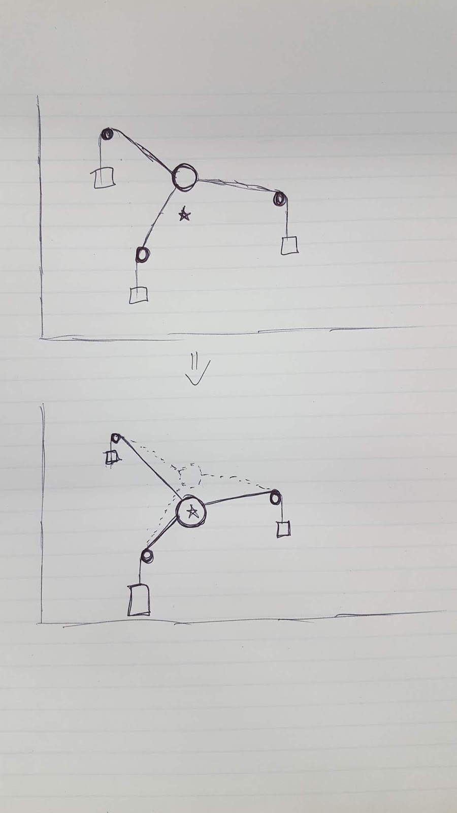
Following the general idea of the kit shown above, the game environment is populated with nodes that apply controllable forces to a central ring object. These forces can be altered to change the position of the ring. The environment will spawn collectibles that the player must direct the ring towards in order to collect them. To move the ring, they will need to intelligently alter the forces applied by the nodes.

Quick sketch of concept
Concept visualization of force body diagram to show how game can function.

Gear Mesh Generating Web Build

Link to Web Build of Prototype Currently

Current Controls
  • Left Mouse Button – Press: Select a gear to make it active
  • Let Mouse Button – Drag: Move selected gear around
  • Left Mouse Button – Drag + Spacebar: Destroy selected gear
  • w : makes the gear spawning object the active object (instead of any gears)
  • Typing in input fields: Changing the number in this input field will alter the corresponding parameter of the currently active (selected) object.

Selecting a gear and changing the value in the input field will immediately change that corresponding parameter on that gear. For example, if you left click a gear, then type the value “1” into the “Body Radius” input field, that gear will have its body radius value immediately change to 1, and its mesh and colliders will update along with it.

There is an invisible gear spawning object (“gear spawner”) that creates a gear when the “Create Gear” button is pressed. The gear created will have values based on whatever the spawner’s current values are. To change the spawner’s values, the spawner must be the active object. This is where the “w” key control comes in. Once the player presses “w”, as long as they don’t left click another gear in the mean time, changes to the input field will become the values of the spawner. Then the next time the “Create Gear” button is pressed, it will use those updated spawner values to create the new gear. This gear can then be altered as any other gear.

Current Issues to Avoid

The input fields do not show the values of an object when it is selected. This can be a bit confusing since it makes it hard to tell what the currently selected object’s values are, unless the player just remembers them. This is something that would be crucial to update as there is currently no way to actually see the current values.

The spawner does initialize at all values of “0”. Just be aware that if you try to create gears before changing the spawner’s parameters, you will be creating invisible empty objects.

When attempting to update the spawner, make sure to press “w” before changing any values in the input fields. This was something I found myself messing up a lot, and would be a feature to improve in the future. Again, make sure to press “w”, and not click any other gears, before changing the input fields to update the spawner’s values.

Example setup of gear mesh generator in Unity’s editor.

DIGM-540 Gear Mesh Generating Resources

  1. Basic Mesh Scripting Tool Description for Unity
  2. Creating Basic Billboard Mesh Through Unity Scripting
    Shows how to create a vertex array, set these into triangles, and create a full mesh.

  3. More Help for Procedural Generation of Mesh

This shows that it is possible to create/modify meshes within Unity using scripting.

Project Direction – Create Script in Unity that Will Take User Inputs to Instantiate a Gear Model Based on Said Parameters

This may be possible through the general use of the Mesh class in Unity scripting. Something along the lines of creating a set of vertices for the central body (some smoothness level of cylinder), then creating a gear tooth mesh that can be multiplied and geometrically positioned around the central core body mesh created.

Bump Mapping

Normal Maps from Unity

“Normal Maps and Height Maps are both types of Bump Map. They both contain data for representing apparent detail on the surface of simpler polygonal meshes, but they each store that data in a different way. A height map is a simple black and white texture, where each pixel represents the amount that point on the surface should appear to be raised. The whiter the pixel colour, the higher the area appears to be raised.

A normal map is an RGB texture, where each pixel represents the difference in direction the surface should appear to be facing, relative to its un-modified surface normal. These textures tend to have a bluey-purple tinge, because of the way the vector is stored in the RGB values.”

Displacement Maps

Unity Displacment Maps and Tesselation

Tri Setup to Create Mesh for Gear Segments
Showing example breakdown of a gear segment in tris.

Randomly Selecting Points within a Given Polygon

References Used:

Stack Overflow – Random Points in a Quadrilateral

Wolfram Alpha Information on Points in a Triangle

I needed to be able to randomly but evenly distribute a number of objects within a 2D area so these are the sources I started with. The Stack Overflow question ended up being a very good starting point, but there were errors with the calculations that I needed to solve in order to actually use their logic.

Fixes from Stack Overflow

First calculation to fix was the originally randomly selected position of the object. It turned out that it was very close, but it actually only worked if v0 was the origin. It was simple enough to fix by adding v0 to the x equation.

The second equation to fix was the v3 equation. They were subtracting v0 twice which is incorrect (again something unnoticeable if v0 is that origin as you’re simply subtracting (0,0) twice). v0 should only be subtracted once to obtain the correct v3 value.

Finally, a correction that was found in the comments was that there are two rotation equations for x’ and the larger one is incorrect. In the text, it can be found that a rotation of pi is necessary. This can be mathematically applied by simply reversing (x – v3) to (v3 – x).

Work to do

Fixing these mathematical errors has appeared to give me the desired results with some further testing required after a final issue. I still need to determine how to let it know mathematically when to “flip” the x position into the x’ position. The original thought was to simply compare the distance from x to v3 and v0, and if it was closer to v3 (distance was less), then apply the x’ flip transformation. This however does not seem to be a geometrically sound solution as I am sometimes getting the flipped applied when it is within the proper bounds.

High Score and Saving Data in Unity: Lessons Learned

I wanted my score and high score text objects to contain text other than solely the score value (in this case it was a simple “Score: ” and “High Score: “). This did lead to a couple issues throughout the debugging process where I realized I didn’t add the extra text when changing/resetting score values, so the extra text would be missing and just the number would be shown. For larger projects, it may be safer and more consistent to make a separate small method for setting a score and/or high score that will add that extra text every time when called (removes a copy/paste step of doing similar actions throughout the scoring script.) And again following a main point from the Board to Bits video, set your key names as string variables within the code so they are easier to consistently call throughout your program.

Saving Data in Unity: PlayerPrefs

Saving Data in Unity: PlayerPrefs – Youtube Link

Youtube tutorial by Board to Bits Games going over the basics of PlayerPrefs in Unity. This shows limitations of PlayerPrefs as something that is mostly useful for storing smaller amounts of data for the player on their system. This also showed a good practice to follow when using key value pairs: set your key as a string variable so that you can call that key variable name every time you need it instead of hoping you type it in exactly correctly every time.

How to Make a High Score in Unity

How to make a HIGH SCORE in Unity by Brackeys

How to make a HIGH SCORE in Unity – Youtube Link

This youtube tutorial from Brackeys shows the bare bones way of getting a high score system started for a game in Unity. It uses the built in PlayerPrefs function to save data to the user’s system.

PlayerPrefs.SetInt and PlayerPrefs.GetInt were used. Playerprefs.SetInt lets you set a key value (which is basically a name for this value when you want to find it) and the actual value to set to this key at the time. Playerprefs.GetInt will return the value stored at the key value given to it, or if nothing is stored within that key location, it will return the default value, which is the second variable value you set when using PlayerPrefs.GetInt.

Altering UI Grid System for Unity 2017

Changing our project from Unity 2018 to 2017 caused a small issue with the UI grid system I created. It relied on a prefab of a UI image object, which 2017 does not play nicely with. They did not take on the positional data assigned to them on instantiation, they would simply keep the transform information of the prefab, so they would all be in the same location which does not create our nice grid.

To get around the need for a prefab, I simply created new gameObjects which then had image components added to them and attached the necessary script since our objects were relatively small and simple. This got around the issue of needing a preexisting object to instantiate in the first place.

These UI image prefabs also had an event trigger attached to them to perform the method to change their color and array value when clicked, so this also needed to be attached or emulated when creating these new objects. Instead of specifically trying to add a pointer click event trigger, I simply added an OnPointerDown method to the script already being attached to the newly created objects that would perform the array value changing method.

Links Referenced for Solution:

UI OnPointerDown Method for Unity
Create UI Elements in Unity

Additional Image Reading Feature for UI Grid Tool

Another feature was added to this tool to help the artists make wall assets for the game, but it also doubles as another option for therapists to create wall poses. The UI grid can intake an image file (a 2D sprite) and output a grid based on the alpha values of individual pixels from this input image. This initially always looked at every pixel, but to help the tool deal with higher resolution (or just larger) images, I also added a resolution factor that would just very simply look at “every x pixels” instead of each individual one. The resolution factor just gets multiplied into the loop looking for pixels.

For example: With resolution factor of 4, the tool will look at pixel numbers: 0 * 4 = 0, 1 * 4 = 4, 2 * 4 = 8, etc.

While this clearly isn’t an amazingly intelligent system, it is a simple way to generally get a roughly similar shape to initially higher resolution images without creating hundreds of thousands of objects.

Creating UI Grid to Build Wall of Objects

Our team wanted to created a tool that could generate walls made of blocks for our “Hole in the Wall” style game. As a health game, we also wanted to have an in game system that a therapist could use to create their own wall objects as well. To satisfy these requests I decided to create a simple UI grid made of images that would tie into a wall generator object in Unity.

Using Unity 2018, I was able to use UI Image prefab objects. The height and width of the wall can be determined in “number of objects”. This will also be reflected in the UI grid object. The user can then click grid elements to either turn them on or off, which will also correspond with a color (white or black). Then when the user clicks the “create wall” button, a wall will be created of 3d objects directly reflecting the UI grid. The wall will have objects where the grid elements are on, and it will just have nothing (a hole) where elements are off.