Intro to Unity’s Shader Graph

September 13, 2019

Unity Shader Graph

Intro Tutorial

Youtube – Basics of Shader Graph – Unity Tutorial

Tutorial #1

By: Brackeys


This tutorial introduces you to Unity’s shader graph, so it starts with the bare minimum and goes over some simple features to get you started. Messing with vertex colors got me back into shaders in Unity, and shader graphs provide a really simple way to get some interesting visual effects when I need a break from trying to figure out shader coding.

I already ran into a lot of snags that kept things from working initially. I missed the step at the beginning of the tutorial where they change the Unity project template to Lightweight RP as they’re creating the project. I was able to get around this by doing what they did in their vertex color tutorial, where I created a Lightweight Renderer Pipeline Asset and dragged that into the Graphics tab of the Project Settings.

I then found out that Unity does not like it when you change the name of a shader. I expected this as a possible issue since scripts need to have some of the coding changed to have the class name match the file name, so this seemed like it could be a similar problem. Since the material/shader still was not working, I simply deleted the shader and made a new one with the proper name and everything was finally displaying as a non-error material.

The general effect they were going for was a glowing effect, so they started with using a Fresnel Effect node in the shader graph. This exactly produces a bit of a glowing effect, with a power value that controls how glowy the material is. We then explored applying colors to node effects like this one. This is done by creating a color node, and multiplying it together with the node you intend to color.

There is an interesting feature in the shader graph that actually lets you open the code and see what it is actually doing behind the scenes. This could be useful for exploring the actual shader code behind the vertex color node I was interested in checking out.

Initially, everything is only controllable within the shader graph, with no way to edit anything directly in the Unity Inspector. You can change this however by right clicking in a node and selecting “Convert to Property”. You can still edit it within the shader graph, but it is now found in the Black Board. This does also show the property in your material so you can have different colored/effected objects using the same base shader graph object.

Finally, they just quickly show that the shader graph can accept and apply textures as well. They just do a simple occlusion example to show this off.

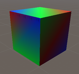
My Final Example Following Tutorial

Vimeo – See Animated Shader

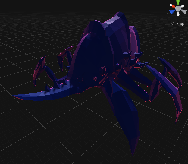
Model: Free Asset from Polygonal Series by Meshtint

PROBLEMS

The shader graph was a bit finicky for me and had weird issues. Some of the previews within the shader graph did not appear for me. I tried ] changing up the graph and opening/closing the shader but they remained gone. I will have to try making a project with a Lightweight RP template from the initial setup to see if that changes any settings that impact this.

Once I promoted the color node to a property, it was hard to actually control the final color on the actual object. Sometimes I would change the color in the Blackboard and it would be reflected on the object, then sometimes it wouldn’t. Then editing the color within the created property on the material would only sometimes change the color. I have not found exactly when it passes the reference from being editable in the shader graph to when it is editable in the material (to sometimes not editable at all), but reapplying the material did seem to fix these issues sometimes.

NEXT STEP

More shader graph tutorials would be nice to check out just to get a basic grasp of how to use it to get some nice effects pretty quickly, although I’d still like to look into the coding of shaders as well. I would also be interested in looking how to tie them together, and control some of the parameters of the shader graph through script.

Brackeys Tutorials: Terrain Generation and Vertex Colors (Cont.)

September 12, 2019

Graphics Tutorials

Mesh Generation/Alteration and Vertex Colors

Youtube – MESH GENERATION in Unity – Basics

Tutorial #1

By: Brackeys


Youtube – PROCEDURAL TERRAIN in Unity! – Mesh Generation

Tutorial #2

By: Brackeys


Youtube – MESH COLOR in Unity – Terrain Generation

Tutorial #3

By: Brackeys


Tutorial #3

Tutorial #3 actually covers UVs and applying textures to surfaces, as well as vertex colors and shaders in Unity. It starts by covering UVs and applying textures, and the main take away is that you want to normalize your UV vectors so they are within the range of [0, 1]. Textures are applied in a normalized fashion when dealing with UVs.

It then gets into setting the vertex colors. This is done by creating a Color array and then simply setting the Mesh.colors of the mesh equal to that array. We created a colors array that was the same size as our vertices, which leads me to believe that a mesh colors array generally has the same number of indices as vertices.

To set the colors, the underlying concept is that the color should correspond to the height of a vertex. This requires some more normalization, which requires us to keep track of the minimum and maximum terrain heights, so that we can use these as our bounds for a [0, 1] range. This is important because we are coloring with a Gradient. Unity has a method that goes with Color and Gradient called Gradient.Evaluate(), which can take in a value between [0, 1] and assign a color based on the given gradient (0 being one end of the color gradient, 1 being the other, and numbers in between being the middle colors or blends).

Once we’ve created the Color array and applied it to our mesh, it does not yet display. This is because most general Unity shaders don’t show this effect. To resolve this, they used Unity’s shader graph to apply the vertex colors to the surface’s actual colors. Using this requires the installation of the Lightweight Render Pipeline and the Shader Graph. You had to create a Lightweight Render Pipeline Asset and drag that into the Graphics section of your Project Settings for reasons that are not explained. You then create a shader with the option of “PBR Graph” to make your shader using the visual node system of the Shader graph. Once there, we just simply added a Vertex Color node and dragged that into the Albedo value of our material to apply the vertex colors.

Example Generated Terrain with Vertex Colors – by me

FURTHER TESTING

I wanted to experiment a bit more with this to see how applying it to some existing meshes could possibly work. I started simple by just using a basic Unity cube. I made a quick script for it that just grabbed a reference to its mesh and went through its entire mesh.vertices array to check exactly how many there were, and there were 24 as I expected {the 8 corners each have 3 vertices, dealing with the 3 different normals of the 3 intersecting faces). I then just made a few public Color options that could be fed into a small 3 color array that would be distributed to vertices around the cube. I applied my material with the created shader, and sure enough, this created the various vertex color effects around my cube.

Here is the script breakdown for this small test: public class CubeVertexColor : MonoBehaviour
{
Mesh mesh;
int vertexCounter = 0;

public Color color1;
public Color color2;
public Color color3;

private Color[] colorArray;
private Color[] vertexColors;

private void Start()
{
mesh = GetComponent().mesh;

colorArray = new Color[] { color1, color2, color3 };
vertexColors = new Color[24];

for(int i = 0; i < mesh.vertices.Length; i++)
{
vertexColors[i] = colorArray[i % 3];
Debug.Log(“The name of this vertex is: ” + mesh.vertices[i]);
vertexCounter = i + 1;
}

mesh.colors = vertexColors;

Debug.Log($”There are {vertexCounter} vertices in the cube mesh.”);
}
}

Example Cube with Vertex Colors – by me

NEXT STEP

I would still like to look into an actual shader script that is able to give similar results for vertex colors. I have gathered some resources today that I will most likely make a post with. I was hoping this could be a helpful tool for creating objects within Unity, but it still seems like it will be easier to make them outside and apply the vertex colors with another software. This will still be helpful in actually displaying those colors though if that is the route I take.

HFFWS – Further Testing Modifying Prefabs Before Instantiation

September 12, 2019

HFFWS Prefab Editing and Instantiation

Testing

TESTING

  • How does altering prefab directly affect process of creating multiple instances?
  • Can altering prefab help set the axis of moving platform?
Can altering prefab help set the axis of moving platform?

Yes, this approach worked. Setting the axis rotation on the prefab directly, THEN instantiating instances of the prefab had the platforms move in the newly set direction.

How does altering prefab directly affect process of creating multiple instances?

This does not appear to have any effect on previously instantiated instances of the prefab. Once an instance is created, changing the parameters of the prefab was NOT changing those parameters for the already instantiated. This gives more support to using this approach

FINAL NOTES

These tests do give this approach more support in being the one to use for now, since it does seem to accomplish all of the goals necessary at this time. It still makes me nervous that the prefab itself gets changed in the editor everytime play is run, and it can impact editor-set prefab instances, so I will continue to check in on different methods for instantiating objects as I move forward.

Brackeys Tutorials: Terrain Generation and Vertex Colors

September 11, 2019

Graphics Tutorials

Mesh Generation/Alteration and Vertex Colors

Youtube – MESH GENERATION in Unity – Basics

Tutorial #1

By: Brackeys


Youtube – PROCEDURAL TERRAIN in Unity! – Mesh Generation

Tutorial #2

By: Brackeys


Youtube – MESH COLOR in Unity – Terrain Generation

Tutorial #3

By: Brackeys


Tutorial #1

This tutorial just covers the basics of creating meshes in Unity. This covers the basics of vertices and tris in Unity, as well as the back-face culling done. This just means when creating tris for the triangle array that they must be input in a clockwise manner to display in the proper direction.

Tutorial #2

This tutorial gets into using the basics of Tutorial #1 to create an entire terrain. This process simply starts by creating a grid of a bunch of vertices, filling them in with tris, and then modifying the positions of some of those vertices.

This started with a process I have used before in mesh generation, where you use several for loops to generate all the vertices in an array of some given size, then fill the gaps between those vertices with tris using more for loops and some basic math. They did add a nice twist where they made the CreateShape method into a coroutine, so we could use WaitForSeconds and see the mesh be filled out. While this was done for a neat aesthetic purpose, this could possibly help in debugging meshes to see where the tris start to be created incorrectly.

The very simple for loop setup for going through all the vertices and filling in the tris did have one flaw that was addressed in the tutorial. When going from the end of a row to the next row, we were creating an extra tri which extended from the end of the row all the way back to the beginning of the next row. Weird errors like this have gotten me before in mesh generation, so I just wanted to point it out.

The setup in this tutorial did the whole quad for each vert, so basically each point was given its own square to cover as we went through the for loops. To avoid the issue of creating extra tris between rows, they simply “skipped” the final vert in each row by adding 1 to the vert index an extra time once a row was completed.

Example of tri generation snippet: for (int z = 0; z < zSize; z++) { for (int x = 0; x < xSize; x++) { triangles[tris + 0] = vert + 0; triangles[tris + 1] = vert + xSize + 1; triangles[tris + 2] = vert + 1; triangles[tris + 3] = vert + 1; triangles[tris + 4] = vert + xSize + 1; triangles[tris + 5] = vert + xSize + 2; vert++; tris += 6; yield return new WaitForSeconds(0.1f); } vert++; // This is the extra vert index added to ensure proper transition from one row to next }

Finally, to make it seem more like the terrain we wanted, we added some noise to the y position of our verts when creating them. Perlin noise was the choice used in the tutorial. Perlin noise is Unity takes in two coordinate parameters, then outputs a noise value between 0 and 1. You can further multiply this by another factor to create more significant noise effects.

There was an interesting issue with using perlin noise. They multiplied the input parameters by 0.3f, which looked very arbitrary. They mentioned that there was a reason for this covered in another video on perlin noise so I checked that and apparently perlin noise repeats on whole numbers. Since we were fedding in parameters based on our vertex indices, these were all whole numbers. Sure enough, when I removed the 0.3f multiplier, the entire terrain was flat again. Something about being “not whole numbers” allows the noise to work.

Tutorial #3

I logged this tutorial earlier, and just wanted to include it here since it went with the other tutorials. I’ll be looking to use this as my Next Step for this post, and hopefully get some more vertex color tutorials to go along with it. I would like to look into some more shader code focused ones if I can since it should be pretty straight forward/simple shader language to get some more practice.

NEXT STEP

Do Tutorial #3 and find more vertex color tutorials (preferably with focus on using shader language).

General Graphics in Unity – Vertex Colors, Shaders, Meshes, UVs

September 11, 2019

General Graphics Information

Meshes, Shaders, Vertices, UVs

Youtube – MESH COLOR in Unity – Terrain Generation

Tutorial #1

Youtube – Learning Shaders in Unity – Everything about Meshes in under 5 Minutes

Info #1

Youtube – Pico Tanks: Vertex shader in Unity

Info #2

Tutorial #1

I was interested at looking into using vertex colors for objects, which led me to a few interesting videos on various aspects of 3D modeling in general. Tutorial #1 was a nice example of using vertex colors in Unity, as well as giving me a simple tutorial to look into on mesh deformation as well. It uses Unity’s shader graph to apply vertex colors, and just simply sets colors with a gradient onto the vertices themselves based on their height (y position).

Info #1

Info #1 was a very brief but general overview of topics on meshes.

  • UVs: It explained how UVs are used to map textures onto faces of objects, which was the biggest topic I had not really covered up to this point. UVs also belong directly to a vertex.
  • Vertices: It also went into how their can be more vertices on an object than you’d expect (since they have a normal that goes with individual faces).

This video was specifically aimed at Unity, so some of the information was most likely Unity specific. For instance, the fact that the Mesh class contains Vertices, Normals, UVs, Tangents, Triangles, and Colors. It finally got into vertex colors at the end, which also showed an example of it being used that just made a very cool colored cube I thought.

From: Info #1

Info #2

Finally, Info #2 was just a very quick video of a game project showcasing their use of vertex shaders to actually move trees in their environment when objects are moving through them. Moving objects affect the colors of an underlying texture map, which use this “color information” to apply affects, such as rotating the trees.

HFFWS – Instantiating Conveyor Belt

September 10, 2019

Human Fall Flat Workshop

Conveyor Instantiation

Today we are finally going to try setting the parameters of a conveyor object on instantiation and seeing which we can and cannot, and trying to fix as many that we cannot as possible. We will also use this as a comparison point for the vertical moving platform generator to start designing the foundation of a tool that can instantiate many different types of objects. At the very least, it could potentially lead to the start of an interface or an abstract class that can be used as the base for classes that instantiate objects.

Parameters to Set on Instantiation

  • Item Prefab
  • Segment Count
  • Length
  • Radius
  • Speed

TESTING

Test #1:

ISSUE: Want to properly set some conveyor prefab parameters on instantiation.

Using a similar start to creating the platform prefabs, my first attempt to instantiate these conveyors began with instantiating the conveyor prefab and casting that as a gameObject. As most of the parameters are found in the Conveyor script in one of the children objects of this prefab, I simply created a Conveyor variable reference that used a GetComponent. I then set all the parameters of this conveyor reference with public variables available in the inspector: segmentCount, lenght, radius, speed.

FAILED: The script was returning an error as soon as it tried to set the first parameter (segment count). This made me think that maybe just using GetComponent to get the Conveyor reference was not working. I thought GetComponent looked through children objects if it didn’t find anything in the initial object, but that may not be the case.

Test #2:

ISSUE: Get prefab reference to actually set conveyor parameters on instantion.

I am changing the GetComponent to GetComponentInChildren to see if specifying that initially helps properly grab the Conveyor reference I need. I am also adding a debug.log to check the name of the reference I am getting in hopes that this will help me check what it is getting (if anything).

SOLUTION: This did fix the problem of getting the reference and actually setting the values, however, this was not creating a conveyor with the proper initialized conditions. The values were being set, but the parameters that need to be set at instantiation to work (like Lenght and Segment Count) were not being received in time.

Test #3:

ISSUE: Parameters being set, but instantiated prefab is not using those set parameters. It is using the default prefab values.

With some very quick checking, I decided to look into issues with changing prefabs and instantiating them and it very simply led me to find that I can just change the prefab parameters itself before instantiating an object. This seemed like a very obvious solution that I hadn’t tried yet apparently, so I simply did just that: I simply had my Conveyor reference variable grab that of the input prefab itself, set all the parameters, and then just instantiate that prefab (without the casting to gameObject addition).

SOLUTION: This immediately worked. The length, radius, and segment count were all set to the inspector values and actually reflected in the instantiated conveyor. It should be noted however that this effect of altering the prefab carries over into the editor AFTER EXITING PLAY MODE.

Images of Prefab Default versus Parameter Altered Instantiation (Conveyor)

Conveyor – Default Prefab
Conveyor – Parameter Set Instantiation

NOTES:

It is very important to note the final effect of editing and instantiating prefabs this way. You are directly modifying the prefab itself, which can have some undesirable effects. At one point, I had an example conveyor in the scene to compare with, and it took on the same parameters of my conveyor spawner after running, ending, and running again, since it must have been using a default prefab reference of some kind. That prefab itself had its values changed (which again, carries over into the editor even when LEAVING PLAY MODE), and my other scene reference to that prefab just took them on as normal prefab changes.

To further test this, I edited the values in the existing prefab instance in the scene slightly, and further play tests did NOT reset this existing prefab reference. I played, closed, played again, and it stayed with the same set values. So it appears any alterations are making it into its own object, where as if you simply drag/drop in a prefab, altering the prefab this way can change how those objects will start up in the future.

Further testing showed that any values directly set to the existing prefab reference in the scene will always stay that set value, but running the game will still cause other parameters that haven’t been altered to change to those dictated by the script. This impact can “lag a play behind” as well. For example, I set the segment count in the existing prefab object to a different value, so playing kept all the parameters the same (even those I had not altered), however, upon playing a second time, those other parameters WERE altered to the values dictated by the script (where the editor set parameter still remained as it was set).

Video of Issue

Vimeo – Video Link

By: Me

The two main ways around using the system this way that I can see are:

  • 1: Always setting the parameters of existing prefabs in the editor that will be affected by scripts
  • 2: Create two seperate prefabs: One for using pre-made instances in the editor and one that can be taken by a random spawner and altered

All of this shows that editing the prefab before instantiation may not be the best solution, and it may be worth looking into other techniques if available.

NEXT STEP

I want to randomly instantiate a few conveyors to make sure the system of setting up random ranges for values works just as well with this as it did for the moving platforms. I would also like to experiment with replacing the meshes with various other mesh objects (for example, instantiating the conveyor segments randomly from a predetermined list of mesh options).

Hex Based 4X Game Tutorial

September 9, 2019

Unity 4X Game Tutorial

Part Based

Mostly Civilized: A Hex-Based 4x Game Engine for Unity – Part 1

Youtube – Link

By: quill18creates

I was looking to add another Unity game genre tutorial that I could follow along with, and happened to come across one for a fairly complex genre I enjoy so this seemed like a nice more advanced tutorial program to go through. I have checked out some of quill18creates content before and it usually serves as some good practice for more advanced topics, while also helping teach you some fundamentals about optimization and general project architecture.

This immediately caught my attention with the hex tile map math shown at the beginning of the video. There they show how to use various coordinate systems, such as cube coordinates, in a hex tile system in a very efficient and sensible way. The link to this information can be found here:

Hexagonal Grids from Red Blob Games

Red Blob Games – Link

Unity – Latest Prefab System 2019 – Nested and Variants

September 5, 2019

Unity Prefabs

Nested Prefabs and Prefab Variants

Youtube – NEW Unity Prefab Workflow – How to use Nested Prefabs

Video #1

Youtube – NEW Prefab Workflow – How to use Unity3D Prefab Variants

Video #2

I have been meaning to learn more about Unity’s latest prefab system updates they put out in Unity 2019, and Unity3D College is a really good place to learn good practices for working in Unity so this seemed like a good place to get some information on the topic. These videos cover both nested prefabs and prefab variants in an in depth manner using some real game object examples to help explain their uses and benefits.

Unity – Accessing All Children Objects Throughout Entire Various Sized Hierarchies

September 4, 2019

Accessing Full Gameobject Hierarchy

Unity

StackOverflow – Get All children, children of children in Unity3d

Link #1

Unity Answers – Find children of object and store in an array

Link #2

For a project we were looking into applying a material color change to some more complex Unity objects/models which are made up of many children objects with many materials. To do this, I needed a way to be able to grab all the materials all throughout a gameobject’s hierarchy and change them simultaneously. This led me to think of a recursive approach, and sure enough there was already one explored that I could reference online in Link #1.

Link #1 also showed me a useful feature that I did not know about Unity. You can use a foreach loop on a transform and it will go through all of the children transforms automatically. This helped make the recursive solution much easier to read, and is just a good feature to know about in the future.

Highlighting a Selected 3D Object in Unity

September 3, 2019

Highlight and Selection

Materials and Color Change

REFERENCES:

Unity – Color.Lerp

By: Unity


Unity – Mathf.PingPong

By: Unity


Youtube – Mini Unity Tutorial – How To Select And Highlight Objects In Game Realtime With C#

Tutorial #1

By: Jimmy Vegas


Youtube – Color.Lerp Unity Once using Coroutines | No Update Function Beginner Tutorial

Tutorial #2

By: iUnity3Dtutorials


Unity Answers – Change color to multiple Materials in one gameObject?

By: Unity (lachesis)


I wanted to create a generic object highlight/selection feature for a project, so I turned to a method I found searching for highligting techniques online where you just change the material color of the currently selected object over time. This is a very simple (conceptually) and often used feature for showing a user what object is currently in focus. It would turn out that it’s a bit more complicated when you are working with models that have many different materials on separate children objects throughout them.

I started with the “Mini Unity Tutorial – How To Select And Highlight Objects In Game Realtime With C#” tutorial as the basis for this system. This was a good inspiration point, but not much more than that. Our project immediately had several major differences so the setup was quite a bit different. To start, we already had a reference to the Interface of the object to highlight, so we wanted to work with this same setup to determine which object is being selected. Our objects are also much more detailed models which are made up of many individual gameobjects which can have several materials each themselves.

Using this as a base, I decided I would setup a basic system that would change the color of an object from its original color to pure white, and then back to its original color. This would then loop until the object was deselected. Conceptually, this is exactly like the tutorial referenced above, but implementing it would take a lot more steps with our current setup.

Casting Interface as Monobehaviour for Gameobject Reference

I first looked into how to reference a gameobject with an existing reference to one of its used interfaces. I found that as long as the script implementing the interface inherits from Monobehaviour on some level, you can cast that interface reference as a Monobehaviour. You can then use this Monobehaviour reference to access that specific gameobject. I could then use this gameobject reference to access the Renderer component to alter the material color.

Looping Color Change for a Single Material

To test the base line of this feature, I wanted to get it working on one object with a single material. I did not like the way Tutorial #1 approached this, so I looked into some other ways to alter the color of a material and came across a Lerp interpretation. I have used Lerp a lot for positional systems, but I had not thought to use it with color, so this seemed perfect. This also makes it very easy to set a final color for the selected object to turn to which can be changed in the design process.

The standard Unity documentation for Lerp with Color also showed me a new Mathf method, which was PingPong. This lets you take a value and constrain it to a specific range between 0 and [length], where [length] is another input parameter. Once that value goes past the input [length], it begins to come back to 0 (as opposed to continuing to increase past [length]). This creates the “ping pong” effect where the input value goes back and forth between 0 and the given length. This works perfectly when lerping back and forth between two colors with an overall range of 0 to 1, where 0 is completely the first color and 1 is completely the second color.

Here is Unity’s basic color Lerp example:
using UnityEngine;

public class Example : MonoBehaviour
{
Color lerpedColor = Color.white;

void Update()
{
lerpedColor = Color.Lerp(Color.white, Color.black, Mathf.PingPong(Time.time, 1));
}
}

Accessing Multiple Materials on a Single Gameobject

So now that I could change the color of a single material, I found that I would actually need to change the color of many materials at once, given the types of models we were working with. I have normally used Renderer.material in Unity to grab the single material on an object, but I found that there is also Renderer.materials, which returns all the instantiated materials of a single object in a single Material array. This is what I would need to get started on accessing all the materials I needed to control.

Since there are many children objects within these models, which can each have several materials of their own, I figured I would need to create some conglomerated Material array that could take on all of the materials while going through a large loop. This loop would need to be able to go through all of the children objects, and grab all the materials from each of those objects as it went through. Then finally, once all of the material references were obtained, we could Lerp all of the materials within this single combined array. Theoretically, it should give the intended result of becoming all white even with all of these materials because they should all be lerping with the same time input and the same final material color.

FINAL NOTES

  • Try Color.Lerp for changing an object’s color
  • Use Mathf.PingPong to have a value go back and forth within a range of 0 to some value
  • Renderer.Materials returns a Material array of all the materials on an object
  • An interface can be cast as a MonoBehaviour to access its gameobject if the interface inherits from MonoBehaviour
  • Complex models can use many different materials, so some basic Unity material techniques can be much more complicated to apply in these cases