March 10th, 2018

Adding Fog of War Effects – Unity

Some full asset tools created that can create fog of war effects

RPG Map Editor – Fog Of War – Youtube

This tool looks to setup a fog effect on a grid based tile system in a 2D game/environment.

Tutorial 3 : Fog of War – Fog of War 3D Effect – Youtube

This tool looks like it uses light to emphasize the fog of war effect, which it can do since it’s set in a 3D environment, which is more commonly associated with lighting in Unity.

March 9th, 2018

Creating Interesting Particle Effects in Unity

Ripple Effects | Unity Particle Effects | Visual FX Tutorial – Youtube

This video is a tutorial on setting up a basic ripple effect using the particle effects given in Unity. This serves as a basic introduction to some of the different parameters of particle systems. This was useful in setting up the visuals for the projectile in our DIGM 530 project Coral Invasion.

Images and Video of Use as Projectile for Project

Video of Projectile in Motion with Audio

Some Useful Notes:
  • As a projectile effect, it was important to make sure to edit the parameter to have the particle gameObject destroy itself once all the particles died.
  • Editing the parameters of lifetime, rate, scaling size/color all useful to fit the particle between two circle colliders.
  • Was able to attach the particle system prefab to the player script exactly like would normally be done for a generic gameObject used as a projectile. Can instantiate particle systems.
March, 4th 2018

Creating 2D Enemy Movement in Unity that is Able to Avoid Obstacles

How can I make an AI that avoids obstacles WITHOUT using NavMesh?

This link contains oStaiko’s answer to the above question, and describes two standard ways to deal with basic enemy AI movement, especially on a 2D plane. These two ways are: a waypoint setup and a more “vision” focused setup.

Waypoint Setup Pros/Cons
  • Good on static maps where enemy can “know” the entire map
  • Deciding fastest routes can be tricky
Vision Setup Pros/Cons
  • Works better for non-static maps/obstacles
  • More difficult to setup (scripting-wise)
  • Better for open maps, can work poorly in more constricted spaces

Example Script for Setting Up Raycast AI to Move Around Obstacles

Unity 3D – Enemy Obstacle Awareness – AI – Code Sample

This link leads to some sample C# code for setting up a script that gives an object raycast vision to avoid obstacles and refocus on a target.

Feb. 27th, 2018

Scripting Enemies to Check Distance for Ranged Attacks – Unity

Scripting is Fun – Unity 2D Game Basics – Enemy AI – Ranged Attack – Youtube Video

This video shows the basic setup for allowing an enemy in a 2D game to rotate, locate player with raycasting and distance tracking, and fire projectiles in the proper direction.

Unity Manuals – Layers

This is placed here for the use of layer masks to control raycasts. Layer masks allow the user to either ignore specific layers with their raycasts, or specifically target layers. This was searched because I had an issue where raycasts where colliding with the object itself and/or the parent object, both of which have colliders.

Feb, 25th, 2018

DIGM 540 Project – Resources

  1. Basic Mesh Scripting Tool Description for Unity
  2. Creating Basic Billboard Mesh Through Unity Scripting
    Shows how to create a vertex array, set these into triangles, and create a full mesh.

  3. More Help for Procedural Generation of Mesh

This shows that it is possible to create/modify meshes within Unity using scripting.

Project Direction – Create Script in Unity that Will Take User Inputs to Instantiate a Gear Model Based on Said Parameters

This may be possible through the general use of the Mesh class in Unity scripting. Something along the lines of creating a set of vertices for the central body (some smoothness level of cylinder), then creating a gear tooth mesh that can be multiplied and geometrically positioned around the central core body mesh created.

Bump Mapping

Normal Maps from Unity

“Normal Maps and Height Maps are both types of Bump Map. They both contain data for representing apparent detail on the surface of simpler polygonal meshes, but they each store that data in a different way. A height map is a simple black and white texture, where each pixel represents the amount that point on the surface should appear to be raised. The whiter the pixel colour, the higher the area appears to be raised.

A normal map is an RGB texture, where each pixel represents the difference in direction the surface should appear to be facing, relative to its un-modified surface normal. These textures tend to have a bluey-purple tinge, because of the way the vector is stored in the RGB values.”

Displacement Maps

Unity Displacment Maps and Tesselation

Tri Setup to Create Mesh for Gear Segments

DIGM530 – Coral Invasion – Sources

Unity – Making 2D Sprite Flash Upon Taking Damage

Make A Sprite Flash? – From Unity

    From gilad905 in this post:
  • Create an animation controller state machine and an animation clip for the flashing state, just like creating a normal animation state.
  • If you want to mix the flashing with another animation (e.g flash while walking), create a new animation layer in the animator and do all below in the new layer. In the new layer’s configuration, make sure it’s set to Blending: Additive (so it won’t override the base layer) and that its weight is set to 1.
  • Enter the animation view (Window -> Animation), chose the wanted GameObject and the empty animation clip you just created. If any properties are already attached to the clip, remove them.
  • Click ‘Add Property’ -> Sprite Renderer -> Enabled -> the ‘+’ icon near it. Using this, you make the object flash by turning SpriteRenderer.Enabled on and off. But for a different effect than flashing, you can use any other property here.
  • In the ‘Samples’ box, write 2 (you only need two samples). The timeline should have a key at 0:0 and another key at 1:0. Insert a new key at 0:1. Make sure that at 0:0 SprireRenderer.Enabled is checked, and on 0:1 it is unchecked.
  • The GameObject should now flash when this state is activated by the animator.

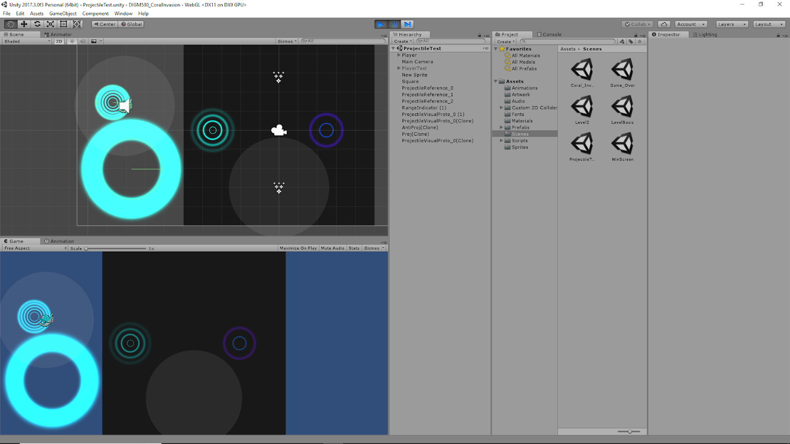
    Unity – Setting Up Animator

    • Followed above instructions to create a basic flashing animation in Unity where the sprite renderer turns off/on once, called TakingDamage
    • Created a second animation just titled IdleCoral, where literally nothing happens
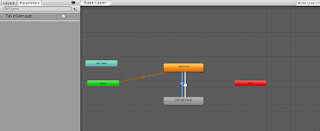
    • Opened the Animator window in Unity
    • Here, I placed my two animations, IdleCoral and TakingDamage
    • Created a link from Entry to IdleCoral, then a back/forth link between IdleCoral and TakingDamage
    • Created a trigger parameter TakeDamage
    • In the script of the base coral, made an anim variable to interact with the TakeDamage trigger
    • That trigger is called in the TakingDamage method of the coral base
    • Since I just wanted the coral to be “idle”, except for taking damage, then return back to idle, the transitions are setup as:
      • IdleCoral to TakingDamage: no exit time, condition: TakeDamage trigger
      • TakingDamage to IdleCoral: Has exit time: this correlates to how many times I want the animation to run (how many flickers of the object I want), fixed duration, conditions: empty
    • Since I do not want the TakingDamage animation to actually take that long to run just to get more flickers, you can directly change the Speed value of the TakingDamage animation itself in the animator to compensate
    • By combining the Exit Time variable of the transition, and the Speed of the animation itself, I can control how many times an animation will play, and how long it will take to run all of those instances of that animation

    Setting Up Multiple Colliders Effectively on Game Objects – Unity

    Setting Up Colliders for 2D Objects

    Important take away from this link from Zaladur:

    “I add an empty child to my characters called “Hitbox” and add a box collider to it, and set it to a Trigger. The Hitbox can be its own layer, and handle collisions with things like bullets, fireballs, or other players or their hitboxes. Meanwhile the parent retains the character controller to handle movement and collision with terrain, obstacles, etc.”

    “Having the hitbox as a trigger allows you to pass through other players while still generating an OnTrigger events so that you can react to hitting an enemy. Just make sure you remember that the Trigger collider is the Hitbox, so you should act on collider.parent if you need to access the actual character.”

    This suggest for 2D game objects, one way to setup colliders is to have your physical collider (non-trigger collider) on the main, parent game object. Then, create a separate game object (called “Hitbox”) as a child to that main gameobject, and give this object a Trigger collider. This gives the overall system of objects a collider that will interact with the environment (walls, ground, other physical bodies if necessary) as well as a separate collider to determine events that occur when certain types of objects collide. This is partnered with labeling the parent collider and the child collider with different layers and/or tags, and use of the 2D collision matrix, to decide if objects physically collide and/or if an event occurs when they collide.

    Example from Coral Invasion currently: Wanted the player to take damage when “colliding” with an enemy, but did not want a true physical collsion to occur. The player and enemy parent game objects have non-trigger colliders, with rigid body components, while their layers are “Player” and “Enemy” respectively. The collision between the layers “Player” and “Enemy” was deactivated in the 2D layer collision matrix. The child objects of these two game objects were each given trigger colliders. The “Player” child was given tag:”Player” and layer:”Player”, but the child of the “Enemy” object was given a tag:”Enemy” and layer:”Default”. As long as the layers were not “Player” and “Enemy”, this allows some type of collision to occur, as that was the only type of collision turned off. Here we have a “Player/Default” collision now. The Enemy child having the tag:”Enemy” was necessary for the OnTriggerEnter2D scripting of how the player object determined if it took damage (this was also why the tag:”Enemy” was removed from the parent Enemy object, as this appeared to be making the player lose double the health upon collision). This all came together so that the player would take damage when colliding with an enemy, but not create any true physical collision of the objects.

    Some further investigation of exactly how this works is needed as the fact that the player was taking double the damage before changing the tag of the Enemy parent object suggests that the player child object was still picking up a collision there, even though it should have technically been a “player/enemy” layer collision. May have something to do with one being a trigger collider and the other being a non-trigger, but unsure.

    Feb. 19th, 2018

    Creating a Basic Cam Model – Maya

    Using Maya, I was able to create a very basic cam mechanism using a basic cylinder as the main body, and moving a few of the edges symmetrically to create a more interesting shape for the follower to follow as it rotated.

    Colliders for Cam in Unity

    Placing Colliders
    1. Use Capsule Collider for main body of Cam (turned sideways, the body of the capsule collider works well as a cylinder collider)
    2. This capsule collider has its radius set to that of the Cam main body, and its height can be adjusted to fit the thickness
    3. Create gameObject – cube
    4. Remove components: Mesh Renderer and Mesh Filter (leaves cube’s collider: this collider has more flexibility for more complex designs)
    5. Set this as a child of the original game object of choice (the gear model in our case)
    6. This was rotated at a 45 degree angle and moved to fit the sharp tear-shaped location of the Cam
    Setting Up Cam-Follower System
    1. Cam Constraints: Frezze Position – x,y,z; Freeze Rotation – x,y
    2. The Cam was given a script to rotate it about its Y-axis
    3. Cam rotation is used to physically drive the follower
    4. Follower Constraints: Frezze Position – x,z; Freeze Rotation – x,y,z
    5. Follower was also affected by gravity, to help physically drive it to follow the cam

    The follower for this cam-follower system is just a generic Unity cube game Object for now, with a basic box collider. This setup appeared to work well for this basic cam-follower mechanism. There was a bit of a difference in the way this cam was imported into Unity as opposed to the gear, which will need looked into. Its polySurface, which contains the mesh of the object, is a separate and child object of the actual “Cam_Basic_Unity” export.

    Driving Gear Mechanisms in Unity with Physics Engine

    The following video shows the cam-follower system in action.

    Example Video of this Cam Animation in Motion

    Feb. 18th, 2018

    Creating Multiple Copies of Models with Different Parameters – Maya

    As was mentioned in the last post, it seems that it was effective to save an original copy of models of mechanisms in Maya with the past transforms and history in tact to edit to create modified versions of said object. Using this, I was able to create another gear that simply had double the radius of the original, and export that model to Unity as a separate object.

    Colliders for Gears in Unity

    Placing Colliders
    1. Create gameObject – cube
    2. Remove components: Mesh Renderer and Mesh Filter (leaves cube’s collider: this collider has more flexibility for more complex designs)
    3. Set this as a child of the original game object of choice (the gear model in our case)
    4. Need to position with local x and z position relative to parent, as well as correct rotation, to fit collider to single gear tooth
    5. Determine angle value (&Theta) between centers of teeth (use 360deg / # of teeth)
    6. Use x = Rcos(&Theta) and z = Rsin(&Theta) (where R is radius of gear object, or centers of colliders)
    7. To use those formulas for all teeth, just use values of: n * &Theta, where n consists of values 1 – # of teeth
    8. You will also want to rotate the colliders around the y-axis equal to the &Theta value used to locate them

    It is important to note that the initial collider may not always be at 0 degrees. It may be offset by several degrees. This was determined by visually lining up the first collider with a few different degrees until it appeared to be correct, then the calculated &Theta values were added to this initially discovered value (instead of the assumed zero).

    Driving Gear Mechanisms in Unity with Physics Engine

    Using the previously described techniques for modeling gears, two gears of different radius values were created to set in Unity (R = 0.5 and R = 1.0). These were all setup with Rigidbody components, and parented to colliders representing all of the teeth, using the above method. Both object’s rigidbody components froze every constraint except for “Rotation on the y-axis (Those frozen include: movement in x,y,z and rotation on x, z). The larger gear was given a basic script that caused it to rotate about the Y-axis over time. It was hoped that this could be placed in a way that rotating this large gear would cause the colliders between the two gears to interact and physically rotate the second gear. Below is a video of it in action.

    Example Video of this Gear Animation in Motion

    Modeling in Maya and Exporting to Unity – Scaling

    Feb. 15th, 2018

    Import/Export Between Maya and Unity – Scaling

    Maya to Unity Scale Guide

    The scaling between Maya and Unity can act a bit strangely. It appears to be because Unity treats its units as “meters” by default, and Maya treats its units in “centimeters” by default. This guide helps in figuring out how to set up your Maya work file and its export, along with the Unity import, so that the scaling of objects makes sense.

    Directly from the guide: “The best reason I can figure from all the posts on the web is that Maya’s native units are centimeters and that is how it “thinks” about its scenes. Anything exporting FROM Maya will essentially be in centimeters, so even though we set the scale of our objects to Meters, they are actually still in centimeters. The FBX, however, doesn’t really care about scale. It will, however, pull the relative scale value out based on what you are trying to export it as. In this case, we have a centimeter based file and we want it to actually be in Meters, so we need to multiply everything by 100 in order to get it sized properly.”

    Maya Models

    Process for creating models in Maya and exporting properly into Unity:

    1. Maya: Windows -> Settings/Preferences -> Preferences
    2. Settings: Change “Working Units” – “Linear” to “meter”
    3. Creates model to a believable size, assuming 1 unit in maya is equivalent to 1 meter
    4. Save this current Maya Scene as a Maya ASCII file that will serve as the base file that can be edited later if necessary to change certain parameters
    5. Once that is done, “Save As” another scene. This will be used for exporting the current setup of the scene
    6. In this second version of the scene, it is good practice before exporting to:
      • Modify -> Freeze Transforms
      • Edit -> Delete All By Type -> History
      • This removes some background clutter from the file before exporting, but they can be useful for later editing/revisions, which is why we save a separate version to access later.
    7. File -> Export All[square] -> File Type: FBX Export, make sure to Edit Preset
    8. Units -> “File units converted to:” centimeters (may also be useful to check FBX File Format and change that type to “ASCII”
    9. Can also edit some other values in this preset: Objects such as Lights and Cameras can most likely be removed from the export process (again, reducing file clutter)
    10. Export All
    11. In Unity, should simply be able to drag and drop your .fbx file into the assets
    12. The “File Scale” of the object will show 0.01, but the transform scale value in Unity should be (1,1,1)
    13. Object should be correct size in Unity!