UnityLearn – AI For Beginners – GOAP – Introduction to GOAP

June 10, 2020

AI For Beginners

Goal Orientated Action Planning (GOAP)

Parts 1, 2, and 3


Beginner Programming: Unity Game Dev Courses

Unity Learn Course – AI For Beginners

Intro

This course covers goal orientated action planning (GOAP) as another way to set up flexible systems of AI behavior. This blog covers the first 3 tutorials of the course which introduce the general GOAP concept by defining its parts and explaining the planning process going in to creating a GOAP system.

An Introduction to GOAP

GOAP Introduction

    Goal Orientated Action Planning (GOAP):

  • has all the elements of a finite state machine, but uses them differently
  • uses graphs for processing
  • GOAPs actions and goals are decoupled
  • actions are free elements in the system that are mixed/matched to meet goals
  • instead of having a list of actions needed to meet a goal, GOAP allows for multiple solutions to be chosen from
Actions

Components: Precondition, Effect
Precondition: state that must be met before the action can take place
Effect: how the action leaves the state of the agent (or world) after the action has occurred
Actions are connected similarly to dominoes where the effects of actions are matched with the preconditions of other actions to create action chains.

Goal: the end state of the agent

Creating a plan comes from understanding the current state of the agent itself and the world around it. The planning stage of GOAP works backwards to see if it is achievable from the currents states (again, of the agent and the world it understands). Since this approach can lead to multiple action chains that lead to the same goal, costs are implemented to help the agent decided which action chain to choose (and in the case of a tie, one can be selected at random).

A general GOAP system follows this structure where actions, goals, and the world state data are fed into a planner. The planner chains actions together according to the goals and starting states to see which plans are achievable. The planner uses the A* algorithm (exactly the same as some pathfinding algorithms) to determine the “best plan”. Once a plan is generated, the agent goes to achieve it with a simple state machine. This state machine looks to simply move the agent where it needs to be to perform the actions necessary, and perform said actions until a goal is achieved. Before each action is performed, it is checked to see if it is valid. If it is not valid anymore, the entire plan is abandoned, and a new plan is generated.

One of the biggest benefits of the GOAP approach is that new actions can continually be added to the pool of available actions for the agent. These actions will then always be picked up by the planner as another possible action to create an action chain or plan to solve a goal. The planner effectively creates the total graphs of actions for the designer, so it is also just easier to program additional factors as complete graphs do not need to be directly programmed as is more common with complete finite state machines.

Setting Up A GOAP Environment

Setting Up A GOAP Environment

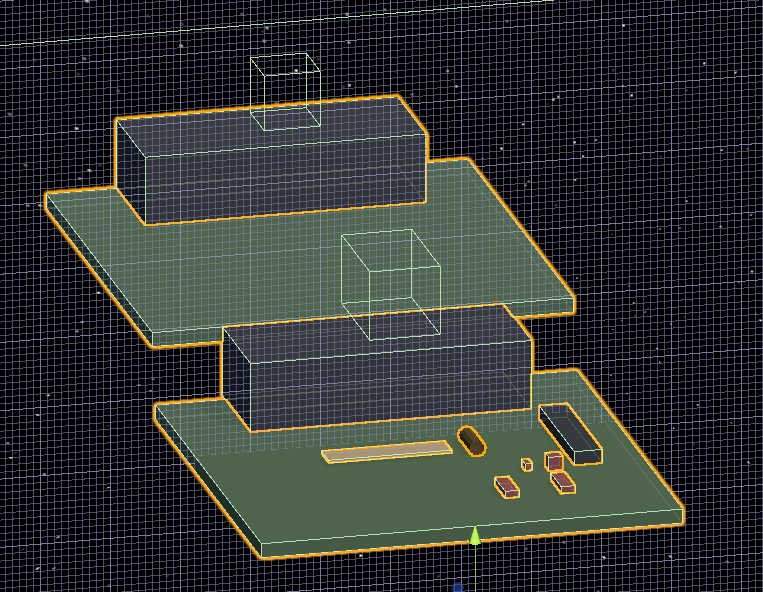
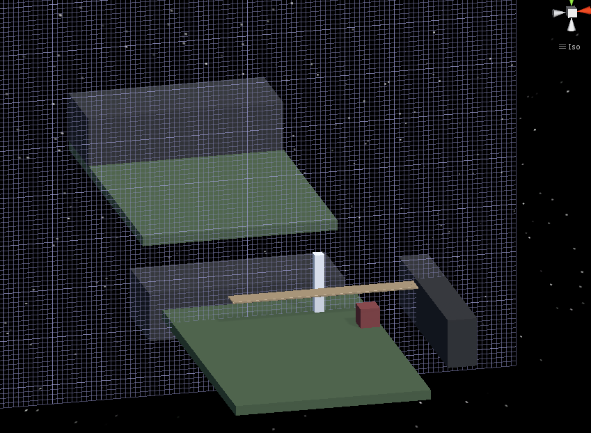
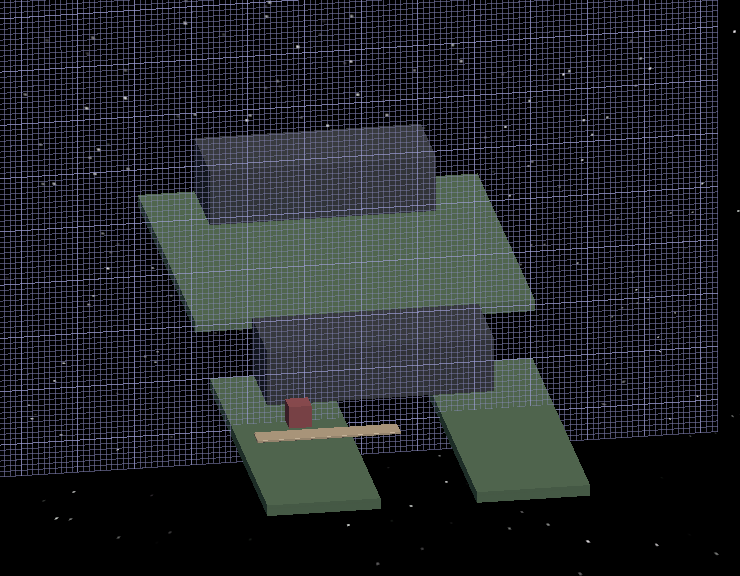
This first major tutorials starts the setup for a basic GOAP project. It is set in a small hospital with patient agents and nurse agents.

Patient Agents

They come into the hospital and get registered at the recption desk. They then move to the waiting room until it is their time to be received by the hospital where they are then brought to a cubicle to be checked on before leaving the hospital.

Nurse Agents

They operate the reception desk receiving incoming patient agents, they come and grab patients from the waiting room to take them to a cubicle to check on them, and they can also rest in the staffing area if they need a break.

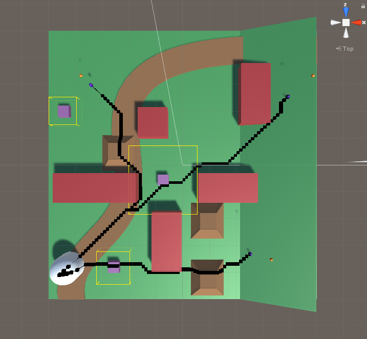
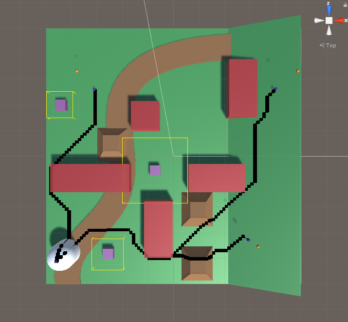
Since a lot of the actions and goals of these two agents are heavily location based, they implemented an underlying waypoint system to the entire setup. Empty gameobjects are set at all the critical locations to be used as waypoints for guiding the agents moving forward. All the waypoints have been tagged with individual unique tags to help the agents locate them immediately upon instantiation.

Pre-Planning the Agent Actions

Pre-Planning the Agent Actions

The foundation of GOAP is that there are: goals, actions, and states. These must all be taken into consideration when planning those which to include and which should be able to lead into others when graphing out plans. An agent has a list of goals it can achieve. It also has a pool of actions it can use to achieve these goals. The actions may also require other actions before being able to be performed. Some actions may also require other agents or some other outside resource.

Patient Actions:
  • Come into hospital
  • Register at the front desk
  • Go to waiting room
  • Get treated when nurse and cubical are available
  • Go home
Nurse Actions:
  • Get Patient
  • Go to Cubicle
  • Rest

The agent must draw information from the world states to help determine what goals are achievable. It will also combine this information with its own state (data it has within itself) to help it determine what is possible. This world state information and the agent state information is passed into the planner, along with all the goal and action options of the agent, so the planner can generate a plan for the agent.

Summary

Overall this felt like a good introduction to the GOAP AI system approach. While I don’t think I could build my own systems quite yet using it, I have a much better understanding of the overall concept and how it can be used to create a flexible set of options for actions for AI’s to use to guide their behavior. The ability to add actions to this pool with relatively little cost is very nice for creating a scalable system with a lot of variability. I could also see this leading to a lot of interesting emergent behavior with large pools of agents, goals, and actions. I look forward to the next parts of the course where they get more into how to program such a system.

Architecture AI Reading CSV File Data to Use in Node Grid

June 8, 2020

Architecture AI Project

Read CSV File

General Goal

For this architecture project we wanted to be able to read data exported from other softwares into Unity. Initially we will be using data from Rhino, but it will be converted to a very generic format (like .csv), so it should be more widely applicable. This data will be used as another way to inform the node system and assign architectural values to these nodes which will again be used to inform the decisions of the agents traveling with the node system.

Using Text Data in Unity

Our text files will be very simplistic, so we can use a very straight forward approach to organizing and using the data from the text files. Each line of data is important for a single node, so splitting on a line will help organize individual node information. Then we just have to split up the information within that line to spread the information out to the proper variables within the node.
Both of these actions can be handled with a string array created from using the Split method at a specific character. Split() is a method within the String class which allows you to easily create separate strings from a single string that is split at a certain location. To create the separate lines of data, the strings are split on the new line character (‘n’), where as when we are splitting up the data within a single line, we split the string on the comma character (‘,’). This specifically works here since we are dealing with .csv files.
This approach pretty easily parsed out the .csv data for me in string format to start using with the node system.

Visualizing Proper .csv Data Distribution on Nodes

I wanted a way to effectively assess and debug whether the system was working properly or not, so I decided to use my node visualization approach I have used for other values already. Using my heat map coloring system for the node visualizer, I just want to visualize the nodes in accordance with their connectivity values (which will be fully applied by the .csv file and the file reader alone).

Actually Applying .csv Data to the Nodes in Grid

This process is much more difficult to find a solution which is quick and somewhat efficient. The original thought of just searching and matching locations blindly would take a very long time every time a grid was initialized, so using the organization of the data to assign these more efficiently will be key.

Approach #1:

Since the .csv data is organized by coordinates in a way similar to how the grid is built in the first place, it made sense to just fill the Node data in from the .csv file data as the grid was built. As long as the .csv data is incremented in a way to continually match the new node positions, this should work rather well.

Issues:

The .csv data is not perfectly rectangular. It does not have values at all for areas where there are gaps or holes, which the node grid does, so it is not just a 1:1 ratio of .csv data points and nodes

Solutions:

  • To keep the data aligned, I am using a check to make sure the current Node having its values assigned matches the coordinates within the current chunk of .csv data looking to be assigned
    • If they match, assign the architectural value (connectivity in testing) and increment the .csv data counter
    • If they do NOT match, do NOT assign the value and do NOT increment the .csv data counter
    • This helps hold on to the .csv data until the proper node is found
    • This must be done very carefully however as if they ever get out of sync, it will basically just stop assigning data forever (because it will just continually wait until the proper node is found)
  • Keeping array indices correct for both sets of arrays is paramount for this system to work
    • The Grid nodes start at 0 and go to (maxDimension – 1)
    • The File nodes start at 1 and go to (maxDimension)
    • The Grid is fully rectangular, where as the File skips coordinates where there is no data
  • Keeping all this in mind, this was the check to keep the arrays straight and assign the proper values to the proper location:
if ((node.gridX + 1) == fullData[dataCounter, 1] && (node.gridY + 1) == fullData[dataCounter, 2])
{
            node.Connectivity = fullData[dataCounter, 3];
            dataCounter++;
        }

    • Just adding 1 to both the x and y dimensions of the grid units makes sure they are in line with the proper data found in the .csv value
    • The dataCounter value keeps track of which row of data to use (which actually ends up reaching the total number of .csv file data nodes (Roughly close to the number of Grid nodes unless there are a lot of gaps))
    • Then the second dimension of the fullData array is simply just the columns of data within the .csv file (so for this basic case, there are only 4 columns)
    • The data from the fullData columns for x and y coordinates are used for the check, then the last column is where the actual value is found that is assigned to the node if the correct one was found
    • The dataCounter is only incremented IF data was actually set
      • This keeps it on the same chunk of data until the proper grid node is found to assign it

Images of Data Visualized

I was able to pass the connectivity data from Rhino into Unity through a .csv file and properly apply that data to the same relative locations within Unity. I overlayed this data with the model that was originally used to generate the data in Rhino, in Unity. I passed the connectivity values into the properly associated nodes as determined by the Rhino .csv value, and then visualized these values on the nodes by coloring them with a heat map-like approach.
I am still using a very basic heat map coloring system that isn’t super clear as the color system I use is cyclical (which means values that are very low and very high both appear reddish), but the images at least show the general idea pretty well. It also shows the gaps are being picked up properly as connectivity values are clearly not assigned there (giving them their base value of 0 which is very low, making those nodes red).

View #1: Node Visualization Over Model

View #2: Node Visualization (without Model)

View #3: Model (without Node Visualization)

Summary / Moving Forward

While this is a good start, it will stay take a lot of work to make the overall system more automated. For example, even this process of keeping the nodes in line with the .csv data is a bit forced because this only works by making the grid have the same dimensions as the .csv data. Further development could help account for cases where you want to scale the system and have more nodes than data points or vice-a-versa.
The models are currently using U.S. units (feet) where as Unity inherently works on the metric system (meters). This immediately presented a bit of a scaling difference just to make sure the data matched up with the actual virtual model. This can make matching everything up exactly a bit tricky because the node system works on an integer system and you can only have whole numbers of nodes, but perfectly matching these systems can result in some fractional values when converting between units, which can end up adding some extra node data around the edges that just isn’t accounted for.

UnityLearn – AI For Beginners – Crowd Simulations – Fleeing

May 22, 2020

AI For Beginners

Crowd Simulations

Part 2


Beginner Programming: Unity Game Dev Courses

Unity Learn Course – AI For Beginners

Intro

I was going to combine both of the end parts of the Crowd Simulation tutorial into one blog, but the Flocking tutorial was rather large and interesting so I decided to break it off into its own post. Because of that, this is a smaller one just focused on the basic fleeing crowd logic.

Fleeing

This is similar to the concept covered with single AI agents, it is just being applied to many agents here. An object is introduced to the environment and the fleeing agents determine the vector towards that object, and set a new course for the exact opposite of that vector.

Key Parameters covered for their flee inducing object:
Radius of Influence – how close agents must be to be affected by the object
Cooldown – how long an agent flees before returning to standard behavior

They decided to induce fleeing by adding a cylinder object to the Nav Mesh environment by clicking. This required adding a mouse button script along with adding a dynamic obstacle to the Nav Mesh again (similar to the FPS controller from the last tutorial).

This tutorial gets into several useful NavMesh methods that have not been used yet. These are helpful references to use when expanding and developing my own pathfinding methods, since they show some useful options to give developers when working with intelligent pathfinding.

There are NavMeshPath objects which hold information about a path for the agent to some given destination. You can set these path objects using the CalculatePath method, using a vector3 position (the destination) and the NavMeshPath object as parameters to set that path with that given destination. This alone does NOT set the agent along this path, it simply gets the information for that path (this is useful for the next step).

They perform a check on the path using fields within the NavMeshPath class and an enum named NavMeshPathStatus before actually setting the new destination of the agent. The check is as follows:

NavMeshPath path = new NavMeshPath();
agent.CalculatePath(newGoal, path);

if(path.status != NavMeshPathStatus.PathInvalid){… }

You are able to access the status of a NavMeshPath with a field within the class. They use this to check that the status of the newly created path is valid by checking it against the PathInvalid option within the NavMeshPathStatus enum. Only after passing this check do they set the newly determined path of the agent. Here, they also show that NavMeshPath has a vector3 array field named corners, which are effectively the waypoints of the path the agent uses for its pathfinding.

Summary

This fleeing logic was pretty basic, but it was helpful to learn a bit more about Nav Mesh in general for Unity. The extra information about NavMeshPath was good to learn about, as well as giving me more options on useful aspects to give my own pathfinding systems.

UnityLearn – AI For Beginners – Crowd Simulations – Flocking

May 22, 2020

AI For Beginners

Crowd Simulations

Part 3


Beginner Programming: Unity Game Dev Courses

Unity Learn Course – AI For Beginners

Intro

This was by far the most interesting crowd simulation tutorial covered in the basic AI tutorials. This one really got into an actual rule based logic system for pathing of agents within a large group to move them in an interesting way with emergent behavior that is still controlled and possible to direct.

Flocking

Part 1

Flocking: simple rules to generate movement for groups of individuals to move towards common goals (i.e. birds or fish)

They create a FlockManager because flock movement requires the individual agents to know about and understand they movement and positioning of all the other agents around them. This will be at a higher level providing data for an entire flock as a whole. This starts with logic to instantiate the flock by creating many fish prefabs in a randomized starting position bound around the FlockManager’s position. They also created a class named Flock to go directly on the the individual fish agents themselves.

    Flocking Rules:

  1. Move towards average position of the group
  2. Align with the average heading of the group
  3. Avoid crowding other group members

Flock Rule 1: Move Towards Average Position of Group

This is done by summing all the positions of the agents within the group and dividing by the number of group members, so it directly is the average position of the agents within the group. The agent’s can then find where they are in relation to this average position, and turn towards it.

Flock Rule 2: Align with the Average Heading of the Group

Similar to rule 1, this is also directly an average within the entire group, but this time it is done using the heading vectors of all the agents within the group. The heading vectors are summed and divided by the total number of agents within a group to determine the group’s overall average heading. The agents then attempt to align their heading with this average heading.

Flock Rule 3: Avoid Crowding Other Group Members

The agents must be aware of the positions of their nearest neighbors and turn away from them, as not to collide with them.

Finally, these three rules produce three vectors which are summed to generate the actual new heading of each individual agent.

new heading = group heading + avoid heading + group position

Back in the Flock class, they start applying some of these rules. Here is a list of some of the variables within their ApplyRules() method and what they represent:

Vector3 vcenter = Vector3.zero; // Average center position of a group
Vector3 vavoid = Vector3.zero; // Average avoidance vector (since avoiding all members in group)
float gSpeed = 0.01f; // Global speed of the entire group (Average speed of the group)
float nDistance; // Neighbor distance to check if other agents are close enough to be considered within the same group
int groupSize = 0; // Count how many agents are within a group (smaller part of the group an individual agent considers neighbors)

When setting up their Flock class and applying these rules, they decided to only apply these rules to neighbor agents. This means that the agents are not directly tied to the entire flock at all times, they simply check for agents within a certain distance around them and they only determine their behavior based on all the agents within that certain radius. I just wanted to clarify since it was unclear if some or all of the rules applied to neighbors or the entire flock (here they just apply all rules to only neighbors).

The summary of the Flock class ending here, specifically within the ApplyRules() method, is that each agent finds all the other agents within the given neighbor distance to determine which agents to momentarily flock with. It sums all the positions of these agents together to eventually get the average position. It then checks if these agents are extraordinarily close to determine if it should avoid them, and if so, calculates the avoidance vector (just the vector directly away from that agent) and sums that into a total avoidance vector (which is NOT averaged later on). It then sums all the speeds of the neighbors, again to average later on.

Finally, it checks if the agent is within a group (so is groupSize > 0), and performs the averaging mentioned earlier here. The new heading is calculated here by summing the average center position of a group with the avoidance vector (and subtracting the agent’s position itself to get a proper vector relative to its current position) and the agent performs a slerp to move towards this new heading.

This created a swirling ball of fish that did not particularly seem to deviate from this large mass with a large number of fish (50) and average values for all the sliders (speeds of 0.25 to 2.5; neighbor distance of ~5; rotation speed ~3.5). While moving, significantly reducing the neighbor distance ( < 1.0) did have them separate into smaller groups and swim off infinitely.

Part 2

Adding General Goal Position for Flock

To help provide the group of agents with a general direction, they added a general goal position to the FlockManager class. The Flock class then uses this position within its average center position calculation to help influence the direction of the agents towards this goal position. Initially they tied this to the position of the FlockManager object itself, and moving this around in the editor moves all the agents tied to it in the general direction towards this object (their goal position).

To automate this process a bit, they have the goal position move randomly every now and then within the given instantiation limits (these are the position ranges which the initial agents spawn in around the FlockManager object). This allows for the agents to move around with some more guidance on their own.

They then extend this random “every now and then” process to the Flock class as well. Here they apply it to randomize the agent’s speed and only run the ApplyRules() method occasionally, so they are not constantly following the flocking rules every single frame. This has the added benefit of reducing the processing intensity as well as the agents will not perform the entire logic of flocking every single frame now.

Returning Stray Agents Back to Flock

They finally add logic to deal with rogue agents that leave the flock and travel outward forever. They use the same bounds which determines the general area to spawn all the agents to determine the greater bounds to contain the agents. The Bounds class within Unity is used to check if the agent is contained within these bounds or not. If not, the agent changes its heading towards the FlockManager’s location instead, which remains intact until it encounters other agents to flock with.

Part 3

Obstacle Detection/Avoidance

The major addition in this final flocking tutorial is the addition of obstacle detection. To accomplish this, they have the individual agents cast a physics ray forward, along their direction of travel, and if it detects an obstacle, it will start to turn they away from it.

To have the agents turn away from an obstacle, they choose to use Unity’s reflect method. Using the hit information of the raycast and the normal information from the object hit, Unity can determiner the reflection vector based on the incoming ray. This produces a vector away from an object at the same angle relative to the normal of the surface as the incoming vector.

Video of the Flocking Result In Action

My Flocking Example

Summary

The implementation and fine tuning of Reynold’s Flocking Rules here was by far the most interesting part of the crowd simulation tutorials in this overall section. The idea of using a set of fairly simple rules on many, many agents in a large group to provide interesting yet realistic motion with controllable direction and emergent behaviors is exactly what I hoped for when looking into crowd behavior, and AI in general.

It was interesting to learn that Reynold’s rules are applied to motion by simply converting each of the three rules into their own vector, and then just summing those vectors for the most part. It is also very cool to see just how much you can change up the behavior and general motion of the agents by altering just a few values, like neighbor distance, speed, and rotation speed.

The additional features they covered after the bare minimum of flocking were also very helpful and practical. Showing ways to control stray agents and move them in a unified general direction towards a common goal are very good additional beahviors to add to flocking, and they were implemented in a very easy to understand way. Obstacle detection is also extremely nice, but its implementation was very straight forward and basic so it wasn’t quite as exciting (although the use of the Unity Reflection method is something I hadn’t used before, so that was helpful to learn).

UnityLearn – AI For Beginners – Crowd Simulations – Moving As One & Creating A City Crowd

May 20, 2020

AI For Beginners

Crowd Simulations

Part 1


Beginner Programming: Unity Game Dev Courses

Unity Learn Course – AI For Beginners

Intro

This is the first part of the Crowd Simulations section of the AI course that I covered. This was the first two major tutorials of four, Moving As One & Creating a City Crowd. These introduce the basic concepts of crowd simulations, and at least cover ways to start moving groups of agents with Nav Mesh Agents in Unity to help visualize these concepts (more so than particularly creating agent crowd AI behaviors yourself).

1: Moving As One

Crowd Behavior: agents move enmasse, as opposed to solely as individual units; their movements are usually also dependent on each other’s movements

Reynold’s Flocking Algorithm:

    Common flocking logic based on 3 simple rules:

  1. Turn towards average heading of group
  2. Turn towards average center of the group
  3. Avoid those around you

They start with a really basic Nav Mesh setup with a bunch of blue capsule agents on one side of a tight corridor, and a bunch of red capsule agents on the other side, and they each need to navigate to a goal on the opposite side, running through/past each group of capsules. The standard Nav Mesh Agent setups with colliders gives interesting group interactions by themselves already to start. This simulation was mostly to help visualize the idea of lines of flow in crowds, as well as instances of turbulence within crowd simulations.

2: Creating A City Crowd

Part 1

Starting setup is adding Street Crowd Simulation package to a Unity project. They included a starting scene of a street with several different characters with basic idle, walk, and run animations. This setup just helps visualize crowd behavior in a more interesting and realistic setting. Initially the agents select a random object from all the objects tagged “goal” as their destination and move there.

The additions done in the tutorial were having the agents continue finding new destinations after reaching the first one and adding more static meshes as obstacles for the agents to move around. The first goal used a distance check for once the agents were close enough to their destination, and then they would select another goal randomly from the initialized goal array. To accomplish the second part, they just added large cubes to simulate buildings to make a more realistic street walking setup with the characters.

Part 2

They added a bunch of buildings to the center of the street scene so agents would walk around the outter edge as normal street traffic.

Alternating Character Animations:

All the characters are using the same animations, so they look strange because they are all doing the exact same animations on the exact same time cycles. To rectify this, they looked into the “Cycle Offset” parameter within the standard walking animation for all the characters in the Animator.

They suggest setting this value with the SetFloat method within Unity’s Animator class. I tried doing this to set the value for the float parameter they added and tied to Cycle Offset, but it was not working for me. The string I entered matches the parameter name, and I connected the value to the parameter as they showed, but it was having no effect for me.

FIXED:

I was able to rectify this issue by explicitly stating within the Random.Range method setting the values to use floats for 0 and 1 (with 0.0f, and 1.0f). Without this explicit declaration, it must’ve been using ints and it was only setting everything to 0 every time (so initializing it as it was originally). Making them floats fixed the issue and they were being put on different cycles as expected.

They also set varied starting speeds for the agents. This included changing the speed of their animations along with their actual Nav Mesh Agent travel speed. To keep these working together well, they just randomly selected a float value and applied this same value to both of these parameters.

Dynamic Nav Mesh Obstacle (with First Person Controller):

They then move on to adding dynamic Nav Mesh obstacles by adding a First Person controller and making the player an obstacle on the Nav Mesh. This is done simply by adding a Nav Mesh Obstacle to the First Person controller. It creates a wireframe similar to a collider that can be shaped and controlled to control the area it removes from the Nav Mesh itself.

Summary

Overall the tutorials have been extremely basic so far and have not really delved into the actual AI behaviours of groups yet really. I am hoping they explore implementing Reynold’s Flocking theorem at some point so I can get some experience with that. If not I may take a detour into the world of “boids” to expose myself to more crowd behavior AIs.

HFFWS Thesis: Hand Built Lever Puzzles to Learn From

April 16, 2020

Hand Building Puzzles

Thesis Project

Intro

Following hand building the ramp puzzles to learn from for my thesis project, I have built lever puzzles to continue the process.

Current Hand Made Ramp Puzzles

As stated previously, this section was about creating the lever puzzles this time around. The main ideas behind them in order are: testing ramps, lift heavy object, build a lever system, launch a projectile, jam lever, and cantilever.

Puzzle 1: Testing

Just as a place holder, I kept a puzzle testing scenario in my Unity project scene just to test physics objects and keep references for ramp angles that work and platform sizes for different scenarios.

Puzzle 2: Lift Heavy Object

This scenario uses a premade seesaw in the scene to allow the player to access new locations. This is the base lever interaction as it gives a really simple environment for the player to focus on playing with a large lever object with their player character and get a base feel for how it operates when masses and forces are applied at different points along the lever. They then eventually use this knowledge to lift a heavy object somewhere with the seesaw they could not reach just by lifting it with the player.

Basic Seesaw Puzzle Scenario


Puzzle 3: Build a Lever System

The resulting puzzle is similar to Puzzle 2, but the player is just given the parts of a lever system to work out how to put them together to create an effective lever. They are given a long platform object to operate as the main body of the lever, as well as several larger massive objects to maneuver in a way to create a fulcrum, support the fulcrum, and even use a weight to hold parts of the system in place while they operate on it.

Building a lever system in HFF can be a bit finicky, so I will need to experiment with what types of masses and objects work best to provide a workable system for the player. This is a very interesting concept overall as it provides a much more insightful application of knowledge for placement of the fulcrum and how it effects the overall system.

Build a Lever Puzzle Scenario


Puzzle 4: Launch Projectile

This puzzle uses a very large difference in mass between two main objects to show transfer of energy in a dramatic fashion. A very small and light object is placed on one end of a lever system, then an extremely massive object is pushed from a great height onto the other end to launch the small object as a projectile to a new location.

Launch a Projectile Lever Puzzle Scenario


Puzzle 5: Jam Lever

These scenarios focus on giving the player an object which they can use to restrict the movement of the lever. Many uses of the scenario focus on adding masses on top of the lever, but this scenario focuses on the player placing masses in the direction of motion of a lever in order to stop it from moving and position it in places it could not otherwise allow them to reach. This can help the player use a lever to cross very long gaps with only minimal mass in objects, since the objects are not used as torque providers.

Jam Lever Puzzle Scenario


Puzzle 6: Cantilever

These scenarios also allow the player to cross significant gaps, by having the player restrict a lever or apply a counter torque to one end of a lever so that it does not move as they move across it (or move another mass across it) as it hangs over a gap. This can be done by hanging a very long platform object over a gap and either setting a very large mass on one end, or jamming the end of the lever under something very static (similar to the inverse of the jam lever scenario above).

Cantilever Lever Puzzle Scenario


Summary

The lever puzzles have already shown to be significantly more complex to setup than the ramp puzzles. The large focus on torque with lever scenarios makes them a lot more complex, as the dimensions of objects as well as their masses need to be coordinated properly to generate solvable scenarios. Messing either of these up will quickly lead to issues where the levers are uncontrollable.

UnityLearn – AI For Beginners – Finite State Machines – Pt.02 – Finite State Machine Challenge

April 6, 2020

AI For Beginners

Finite State Machines

Finite State Machines


Beginner Programming: Unity Game Dev Courses

Unity Learn Course – AI For Beginners

Finite State Machine Challenge

This tutorial provided a challenge to complete and then provided a solution. The challenge was to create a state where the npc would retreat to an object tagged as “Safe” when the player approached the NPC closely from behind.

My Approach

Since they had a State enum named Sleep already that we had not worked with yet, I used that as the name of this new state (I started with Retreat, but then found the extra Sleep enum so I changed to that since I assumed it would be more consistent with the tutorial). Similar to the CanSeePlayer bool method added to the base State class for detecting when the player is in front of the NPC, I added an IsFlanked bool method here that worked similarly, but just detected if the player was very close behind instead of in front. I used this check in the Patrol and Idle state Update methods to determine if the agent should be sent into the new Sleep state.

In the Sleep state itself I used similar logic from the Pursue state for the constructor, so I set the speed to a higher value and isStopped to false so the NPC would start quickly moving to the safe location. In the Enter stage I found the GameObject with tag “Safe” (since this was set in the conditions for the challenge to begin with) and used SetDestination with that object’s transform.position.

The Update stage simply checked if the npc got close to the safe object with a continuous magnitude vector check, and once it got close enough, it would set the nextState to Idle before exiting (since Idle quickly goes back to Patrol in this tutorial anyway, this is the only option really needed).

Finally, the Exit stage just performs ResetTrigger for isRunning to reset the animator and moves on to the next State (which is only Idle as an option at this time).

Their Approach:

Most of what they did was very similar, although they did make a new State named RunAway instead of the extra Sleep State, so I could have stuck with Retreat and been fine.

Notable differences were that they checked if the player was behind them by changing the order of subtraction when performing the direction check (changed player – npc to npc – player) where I just had the angle check use the negative forward vector of the npc instead of the positive vector. These give effectively the same results, but I liked my approach better since it matched up with what was actually being checked better.

They also set the safe gameObject immediately in the constructor, where I was setting this in the Enter stage of the State. Again, this basically gives the same results in most cases, but I think their approach was better here just because the sooner you perform and set that FindGameObjectWithTag the better I think just to make sure it has access when it does need it.

Finally, for their distance check to see if they had arrived at the safe zone, they used a native NavMeshAgent value, remainingDistance. I used the standard distance check of subtracting the vectors and checking the magnitude, so these again both give similar results. Mine is more explicit in how it is checking, and the NavMeshAgent value is just cleaner, so these both had pros and cons.

Summary

This was a nice challenge just to work with a simple existing finite state machine. Similar to what they mentioned in the tutorial, I think setting the safe object in the static GameEnvironment script and just pulling from that (instead of using FindGameObjectWithTag every time the NPC enters the Sleep/RunAway State) would be much more efficient. Also just to help with checking states and debugging, I added a Debug.Log for the base State Enter stage method that just returned the name of the current State as soon as it was entered each time. This let me know which State was entered immediately when it was entered, so this also helped show me when the states were entered, so this was a very nice state machine check that only required a single line of code.

UnityLearn – AI For Beginners – Finite State Machines – Pt.01 – Finite State Machines

April 1, 2020

AI For Beginners

Finite State Machines

Finite State Machines


Beginner Programming: Unity Game Dev Courses

Unity Learn Course – AI For Beginners

Finite State Machines

Finite State Machine (FSM): conceptual machine that can be in exactly one of any number of states at any given time.
Represented by a graph where nodes are the states, and the paths between them are the transitions from one state to another. An NPC will stay in one state until a condition is met which changes it to another state.

Each state has 3 core methods: Enter, Update, Exit

  • Enter: runs as soon as the state is transitioned to
  • Update: is the continuous logic run while in this state
  • Exit: run at the moment before the NPC moves on to the next state

State Machine Template Code (Can use core of this for each individual state):

public class State
{
public enum STATE
{
IDLE, PATROL, PURSUE, ATTACK, SLEEP
};

public enum EVENT
{
ENTER, UPDATE, EXIT
};

public STATE name;
protected EVENT stage;

public STATE()
{ stage = EVENT.ENTER; }

public virtual void Enter() { stage = EVENT.UPDATE; }
public virtual void Update() { stage = EVENT.UPDATE; }
public virtual void Exit() { stage = EVENT.EXIT; }

public State Process()
{
if (stage == EVENT.ENTER) Enter();
if (stage == EVENT.UPDATE) Update();
if (stage == EVENT.EXIT)
{
Exit();
return nextState;
}
return this;
}
}

Creating and Using A State Class

State class template (similar but slightly different from last tutorial, with some comments):

public class State
{
public enum STATE
{
IDLE, PATROL, PURSUE, ATTACK, SLEEP
};

public enum EVENT
{
ENTER, UPDATE, EXIT
};

// Core state identifiers
public STATE name;
protected EVENT stage;

// Data to set for each NPC
protected GameObject npc;
protected Animator anim;
protected Transform player;
protected State nextState;
protected NavMeshAgent agent;

// Parameters for NPC utilizing states
float visionDistance = 10.0f;
float visionAngle = 30.0f;
float shootDistance = 7.0f;

public State(GameObject _npc, NavMeshAgent _agent, Animator _anim, Transform _player)
{
npc = _npc;
agent = _agent;
anim = _anim;
stage = EVENT.ENTER;
player = _player;
}

public virtual void Enter() { stage = EVENT.UPDATE; }
public virtual void Update() { stage = EVENT.UPDATE; }
public virtual void Exit() { stage = EVENT.EXIT; }

public State Process()
{
if (stage == EVENT.ENTER)
Enter();
if (stage == EVENT.UPDATE)
Update();
if(stage == EVENT.EXIT)
{
Exit();
return nextState;
}
return this;
}
}

Notice that the public virtual methods for the various stages of a state look a bit awkward. Both Enter and Update set the stage to EVENT.UPDATE because you want them to be setting stage equal to the next process called, and both of them would look to move that to Update. After entering, you move to Update, and each Update wants to move to Update again until it is told to do something else to Exit.

They also started to make actual State scripts, which create new classes that inherit from this base State class. The first example was an Idle state with little going on to get a base understanding. Each of the stage methods (Enter, Update, Exit) used the base versions of the methods from the base class as well as their own unique logic particular to that state. Adding the base methods within just ensured the next stage is set properly and uniformly.

Patrolling the Perimeter

This tutorial adds the next State for the State Machine, Patrol. This gets the NPC moving around the waypoints designated in the scene using a NavMesh.

They then create the AI class, which is the foundational logic for the NPC that will actually be utilizing the states. This is a fairly simple script in that the Update simply runs the line:

currentState = currentState.Process();

This handles properly setting the next State with each Update, as well as deciding which state to use and which stage of that state to run.

It turns out running the base Update method at the end of all the individual State classes’ Update methods was overwriting their ability to set the stage to Exit, so they could never leave the Update stage. They fixed this by simply removing those base method calls.

Summary

Using Finite State Machines is a clean and organized way to give NPCs various types of behaviors. It keeps the code clean by organizing each state of behaviors into its own class and using a central manager AI for each NPC to move between the states. This also helps ensure an NPC is only in a single state at any given time, to reduce errors and debugging.

This setup is similar to other Finite State Machine implementations I have run into in Unity. The Enter, Update, and Exit methods are core in any basic implementation.

A* Architecture Project – Spawning Agents and Area of Influence Objects

March 25, 2020

Updating A*

Spawn and Area of Influence Objects

Spawning Agents

Goal: Ability to spawn agents in that would be able to use the A* grid for pathing. Should have options to spawn in different locations and all use grid properly.

This was rather straight forward to implement, but I did run into a completely unrelated issue. I created an AgentSpawnManager class which simply holds a prefab reference for the agents to spawn, a transform for the target to pass on to the agents, and an array of possibl spawn points (for incorporating the option of several spawn locations). This class creates new gameObjects based on the prefab reference, and then sets their target to that determined by the spawner. This was something worth tracking since sometimes there can be issues with Awake and Start methods when setting values after instantiation.

This was all simple enough, but the agents were spawning without moving at all. It turns out the issue was that the spawn location was above a surface that was above an obstacle (the obstacle was below the terrain, but entirely obstructed). This was an issue with how my ray detection and node grid was setup.

Editing the Grid Creation Raycast

The node and grid creation for the A* system uses a raycast to detect obstacles, as well as types of terrain to inform the nodes of their costs or if they are usable at all. Since it is very common to use large scale planes or surfaces as general terrain, and place obstacles on this, uses a full ray check would almost always pick up walkable terrain, even if it hit an obstacle as well.

To get around this, I simply had it check for obstacles first, and if it detected one, mark this node unwalkable and move on. This created an issue however in the reverse case, if an obstacle went a bit past the terrain into other nodes below the surface, they would be picked up as false obstacles, or in this case, it was picking up obstacles that were entirely located below the surface.

I was using a distance raycast in Unity, which just checks for everything over a set distance. I looked into switching this to a system that just detects the first collider the ray hits and simply use that information. I found that using the hit information of the raycast does this.

Unfortunately I am using a layer setup for walkable and unwalkable (obstacle) terrain, so I needed to incorporate that into my hit check. Checking layers is just weird and unreadable in Unity scripting, since I am currently just use the hardcoded integer value for the current layer number that is unwalkable when doing my check for obstacles. This does at least suffice to let the system work properly for now.

Influence Area with Objects

I wanted to be able to create objects which could influence the overall cost of nodes around them in an area significantly larger than the objects themselves. The idea is that a small but visible or detectable objects could influence the appeal of nodes around them to draw or push agents away from them.

For a base test, I created a simple class called Influence to place on these objects. The first value they needed was an influence int to determine how much to alter the cost of the nodes they reached with their influence. Then, to determine the influence range, I gave them an int each for the x and z direction to create dimensions for a rectangle of influence in units of nodes. I also added some get only variables to help calculate values from x and z to help center these influence areas in the future.

I then added an Influence array to the AGrid class which contains all the logic on initializing the grid of nodes and setting their values at start up. After setting up the grid, it goes through this array of Influence objects and uses their center transform positions to determine what node they are centered on, then finds all the nodes around it according to the x and z dimensions given to that influence object, and modifies their cost values with the influence value of the Influence object. Everything worked pretty nicely for this.

As a final touch just to help with visualization, I added a DrawGizmos method that draws yellow wire cubes around the influence objects to match their area of influence. Since the dimensions are mainly in node units, but the draw wire cube wants true Unity units, I simply multiplied the x and z node dimensions for the influence by the nodeDiamater (which is the real world size of each node) to convert it to units that made sense.

I have two sample images to show the influence objects in effect below. The small purple squares are the influence objects, and the yellow wire frame cubes around them show their estimated area of influence. The first image shows the paths of the agents when the influence of all squares is set to 0 (no influence), and the second shows the paths when the influence is set to 200 (makes nodes around them much more costly and less appealing to travel over).

Paths with Influence Set to 0


Paths with Influence Set to 200

Summary

The raycast and layer system for detecting the terrain and initializing the grid could use some work to perform more cleanly and safely, especially for future updates. The spawning seems to have no issues at all, so that should be good to work with and edit moving forward. The basic implementation of the influence objects has been promising so far, I will look into using that as a higher level parent class or an interface moving forward as this will be a large part of the project and their may be many objects that use this same core logic by want special twists on it (such as different area of influence shapes, or various calculations for how influence should be applied).

UnityLearn – AI For Beginners – Waypoints and Graphs – Pt.01 – Graph Theory

March 24, 2020

AI For Beginners

Graph Theory

Graph Theory


Beginner Programming: Unity Game Dev Courses

Unity Learn Course – AI For Beginners

Graph Theory

Intro

The AI for Beginners course starts very basic so I have not covered a lot up until now. It handles the basics of moving an object with simple scripting, as well as guiding and aiming that movement a bit. This section starts to get into some more interesting theory and background for AI.

Graphs are simply collections of nodes and edges. Nodes are locations or points of data, and edges are the paths connecting them (which also contain significant data themselves). There are two directional types for edges within these graphs: directed and undirected. Directed paths only allow for movement between two nodes in a single direction, while undirected paths allow for movement either direction between nodes.

Graphs are used in any case to move between states. These states can be real states or conceptual states, so the nodes and edges between them can possibly be much more theoretical then actual objects or locations.

Utility Value: This is the value for an edge. Some examples shown were time, distance, effort, and cost. These are values that help an NPC make a decision to move from one node to the next over said edge.

Basic High Level Algorithms for Searching Nodes

Breadth-First Search

Marks original node as 1, then all adjacent nodes to that as 2, then all adjacent nodes to all of those as 3, etc. until it reaches the destination node. It then counts backwards to determine the path. Examines all possible nodes in graph to find the best path. This makes it effective but expensive and time consuming.

Depth-First Search

Starts at NPC position, then finds one adjacent node and numbers it, then it finds another single adjacent node and numbers it. This continues until it finds a dead end, in which case it returns to the last node where there was another direction to try and heads off in a different direction with the same method.

More Advanced General High Level Algorithm

A* Algorithm

All the nodes are numbered. It creates an open list and closed list, which keep track of nodes visited. There are three main cost values associated with the edges in this case: Heuristic cost (H cost), Movement cost (G cost), and the F cost.
Heuristic Cost (H Cost): estimated cost of getting to the destination from that specific node (this value is generally distance related)
Movement Cost (G cost): utility cost of moving from one node to another node
F Cost: sum of the H cost and G cost which determines the total value of that node
Each node stores these cost values as well as its parent, which is the closest node that continues the proper path. Once the final node is reached, the nodes follow this chain of parent nodes to determine which nodes make up the path to travel.

Summary

This was a very simplified approach to graph theory that was at the very least helpful as a small refresher on how A* worked. I also learned that Unity’s NavMesh uses the A* algorithm at its foundation. This does give me a good starting point with some subjects and terminology to investigate to understand some theory behind AI however, with graph theory, the nodes and edges, and the basic search methods.