Feb. 19th, 2018

Creating a Basic Cam Model – Maya

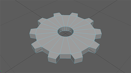
Using Maya, I was able to create a very basic cam mechanism using a basic cylinder as the main body, and moving a few of the edges symmetrically to create a more interesting shape for the follower to follow as it rotated.

Colliders for Cam in Unity

Placing Colliders
  1. Use Capsule Collider for main body of Cam (turned sideways, the body of the capsule collider works well as a cylinder collider)
  2. This capsule collider has its radius set to that of the Cam main body, and its height can be adjusted to fit the thickness
  3. Create gameObject – cube
  4. Remove components: Mesh Renderer and Mesh Filter (leaves cube’s collider: this collider has more flexibility for more complex designs)
  5. Set this as a child of the original game object of choice (the gear model in our case)
  6. This was rotated at a 45 degree angle and moved to fit the sharp tear-shaped location of the Cam
Setting Up Cam-Follower System
  1. Cam Constraints: Frezze Position – x,y,z; Freeze Rotation – x,y
  2. The Cam was given a script to rotate it about its Y-axis
  3. Cam rotation is used to physically drive the follower
  4. Follower Constraints: Frezze Position – x,z; Freeze Rotation – x,y,z
  5. Follower was also affected by gravity, to help physically drive it to follow the cam

The follower for this cam-follower system is just a generic Unity cube game Object for now, with a basic box collider. This setup appeared to work well for this basic cam-follower mechanism. There was a bit of a difference in the way this cam was imported into Unity as opposed to the gear, which will need looked into. Its polySurface, which contains the mesh of the object, is a separate and child object of the actual “Cam_Basic_Unity” export.

Driving Gear Mechanisms in Unity with Physics Engine

The following video shows the cam-follower system in action.

Example Video of this Cam Animation in Motion

Feb. 19th, 2018

Research – Learning Physics Modeling with PhysX – Book

This is a book by Krishna Kumar going over the basics of PhysX as a physics engine. Could be useful for better understanding the default physics engine, PhysX, to properly drive engineering mechanisms.

Research – Book – Engineering Finite Element Analysis

“Finite element analysis is a basic foundational topic that all engineering majors need to understand in order for them to be productive engineering analysts for a variety of industries. This book provides an introductory treatment of finite element analysis with an overview of the various fundamental concepts and applications. It introduces the basic concepts of the finite element method and examples of analysis using systematic methodologies based on ANSYS software.”

This could be useful for learning and using finite element analysis, if looking into real time finite element analysis for use in games.

List of Physics Engines

Wikipedia page for Physics Engines

Real-Time
  • PhysX
  • Bullet
  • Havok
  • Vortex
High Precision
  • VisSim
  • Working Model
Feb. 18th, 2018

Creating Multiple Copies of Models with Different Parameters – Maya

As was mentioned in the last post, it seems that it was effective to save an original copy of models of mechanisms in Maya with the past transforms and history in tact to edit to create modified versions of said object. Using this, I was able to create another gear that simply had double the radius of the original, and export that model to Unity as a separate object.

Colliders for Gears in Unity

Placing Colliders
  1. Create gameObject – cube
  2. Remove components: Mesh Renderer and Mesh Filter (leaves cube’s collider: this collider has more flexibility for more complex designs)
  3. Set this as a child of the original game object of choice (the gear model in our case)
  4. Need to position with local x and z position relative to parent, as well as correct rotation, to fit collider to single gear tooth
  5. Determine angle value (&Theta) between centers of teeth (use 360deg / # of teeth)
  6. Use x = Rcos(&Theta) and z = Rsin(&Theta) (where R is radius of gear object, or centers of colliders)
  7. To use those formulas for all teeth, just use values of: n * &Theta, where n consists of values 1 – # of teeth
  8. You will also want to rotate the colliders around the y-axis equal to the &Theta value used to locate them

It is important to note that the initial collider may not always be at 0 degrees. It may be offset by several degrees. This was determined by visually lining up the first collider with a few different degrees until it appeared to be correct, then the calculated &Theta values were added to this initially discovered value (instead of the assumed zero).

Driving Gear Mechanisms in Unity with Physics Engine

Using the previously described techniques for modeling gears, two gears of different radius values were created to set in Unity (R = 0.5 and R = 1.0). These were all setup with Rigidbody components, and parented to colliders representing all of the teeth, using the above method. Both object’s rigidbody components froze every constraint except for “Rotation on the y-axis (Those frozen include: movement in x,y,z and rotation on x, z). The larger gear was given a basic script that caused it to rotate about the Y-axis over time. It was hoped that this could be placed in a way that rotating this large gear would cause the colliders between the two gears to interact and physically rotate the second gear. Below is a video of it in action.

Example Video of this Gear Animation in Motion

Modeling in Maya and Exporting to Unity – Scaling

Feb. 15th, 2018

Import/Export Between Maya and Unity – Scaling

Maya to Unity Scale Guide

The scaling between Maya and Unity can act a bit strangely. It appears to be because Unity treats its units as “meters” by default, and Maya treats its units in “centimeters” by default. This guide helps in figuring out how to set up your Maya work file and its export, along with the Unity import, so that the scaling of objects makes sense.

Directly from the guide: “The best reason I can figure from all the posts on the web is that Maya’s native units are centimeters and that is how it “thinks” about its scenes. Anything exporting FROM Maya will essentially be in centimeters, so even though we set the scale of our objects to Meters, they are actually still in centimeters. The FBX, however, doesn’t really care about scale. It will, however, pull the relative scale value out based on what you are trying to export it as. In this case, we have a centimeter based file and we want it to actually be in Meters, so we need to multiply everything by 100 in order to get it sized properly.”

Maya Models

Process for creating models in Maya and exporting properly into Unity:

  1. Maya: Windows -> Settings/Preferences -> Preferences
  2. Settings: Change “Working Units” – “Linear” to “meter”
  3. Creates model to a believable size, assuming 1 unit in maya is equivalent to 1 meter
  4. Save this current Maya Scene as a Maya ASCII file that will serve as the base file that can be edited later if necessary to change certain parameters
  5. Once that is done, “Save As” another scene. This will be used for exporting the current setup of the scene
  6. In this second version of the scene, it is good practice before exporting to:
    • Modify -> Freeze Transforms
    • Edit -> Delete All By Type -> History
    • This removes some background clutter from the file before exporting, but they can be useful for later editing/revisions, which is why we save a separate version to access later.
  7. File -> Export All[square] -> File Type: FBX Export, make sure to Edit Preset
  8. Units -> “File units converted to:” centimeters (may also be useful to check FBX File Format and change that type to “ASCII”
  9. Can also edit some other values in this preset: Objects such as Lights and Cameras can most likely be removed from the export process (again, reducing file clutter)
  10. Export All
  11. In Unity, should simply be able to drag and drop your .fbx file into the assets
  12. The “File Scale” of the object will show 0.01, but the transform scale value in Unity should be (1,1,1)
  13. Object should be correct size in Unity!

Sources for Basic Gear Equations and Parameters

Feb. 15th, 2018

Gear Equations

Basic Gear Equations

The basics of gear ratios.

Gear Parameters

Gear Parameters

This site includes a list of many parameters involved in gear design, and some of the general equations to obtain them.

Types of Gears

Types of Gears

This site shows all of the different types of gears and gear mechanisms in a very basic fashion with short descriptions of the general uses for each of them.