Unity Shader Graph – Signed Distance Fields – Update with Subgraph Fix

June 24, 2021

Shader Graph

Unity


Title:
Drawing Boxes and Rectangles in URP Shader Graph with 2D SDFs! 2021.1 | Unity Game Dev Tutorial

By:
Ned Makes Games


Youtube – Tutorial

Description:
Exploration into calculating signed distance fields and using them with Unity’s Shader Graph.


Title:
Rectangle SDFs and Procedural Bricks! Video Production Stream | Unity Game Dev Livestream

By:
Ned Makes Games 2


Youtube – Tutorial

Description:
The full stream which most of the previous tutorial is pulled from. Useful for any more in depth questions of previous tutorial.


Overview

When I visited this tutorial yesterday I ran into an issue with Unity 2021.1.3 that working with subgraphs was extremely bugged and error prone. I had seen online that later versions potentially fixed the issue, so I download the latest version, 2021.1.12, and this did indeed fix the issue for me, making this tutorial much easier to follow along with.

This tutorial was mostly just looking at the subgraphs and shader graphs they built and following along to build them out myself. This was at least a decent learning experience at getting familiar with the work flow of setting up subgraphs for your shader graphs, as well as just using a lot of the math nodes.

Helper Scripts to Show Off Shader

Along with building the shader, they made two simple scripts to make the shader a bit interactive and more flexible.

SetPoints

This class was responsible for letting the user move the two points dictating the general length of the rectangle shape by just clicking and dragging. This however did not work immediately, as they were using a helper class named MousePointer I did not use.

I was able to get a similar result by replacing their process of getting the point:


var p = MousePointer.GetWorldPosition(Camera.main);


with my replacement:


var p = Camera.main.ScreenToWorldPoint(new Vector3(Input.mousePosition.x, Input.mousePosition.y, distanceToPlane));

distanceToPlane was a value the user could put in that is the distance from the camera to the flat plane the camera is facing to test the shader. As long as the exact same distance is put there for the z-value of ScreenToWorldPoint, the points moving correlate exactly with where the user is dragging them.

RectangleThicknessByScrollWheel

This class lets the user control the thickness, or width, of the rectangle with the scroll wheel. This class directly worked as shown.

General Notes with Scripts Interacting with ShaderGraph Properties

Integrating the scripts with the Shader Graph properties was actually pretty easy. It worked similarly to working with the Animator in Unity. You just use methods like SetFloat() and give it two parameters where one is the exact string name of the property you want to set, and the second is the value you are passing in to said property. It is worth noting this was just accessed through the Material, there was no strange Shader Graph object that needed to exist or anything like that.

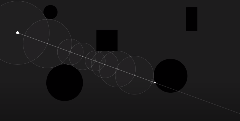
An example of my implementation of the tutorial can be seen below.


Unity Shader Graph: SDF Rainbow Pulse from Tutorial by NedMakesGames from Steve Lilley on Vimeo.

Video Example of my Following of the Pulse Shader in the Ned Makes Games Tutorial

via Blogger http://stevelilleyschool.blogspot.com/2021/06/unity-shader-graph-signed-distance_24.html

Unity Shader Graph – Signed Distance Fields and Subgraph Errors

June 23, 2021

Shader Graph

Unity


Title:
Drawing Boxes and Rectangles in URP Shader Graph with 2D SDFs! 2021.1 | Unity Game Dev Tutorial

By:
Ned Makes Games


Youtube – Tutorial

Description:
Exploration into calculating signed distance fields and using them with Unity’s Shader Graph.


Overview

This shader tutorial quickly explores calculating signed distance fields and using that for interesting effects. These effects were built in HLSL in the tutorial video originally, but they also show how these can be implemented with Unity’s Shader Graph system. I wanted to use the Shader Graph approach, but unfortunately I found that Unity’s Shader Graph Subgraphs have some major issues.

Signed Distance Fields (SDFs)

Signed Distance Fields (SDFs): calculate the distance from any arbitrary point to a specific shape

Principles of Calculating

To start, they look at an example using a rectangle whose center is at the origin (0, 0).

First, they find the distance from the point, p, to the center of the rectangle, which is just the length of the Vector2 p because the center is at the origin.

Then, using the symmetry of the rectangle, the absolute value of point, p, and the half dimensions of the rectangle are used to determine the distance of the point to any corner of the rectangle.

To get the positive results, they find the vector between the absolute value of point, p, and the corner of the rectangle and find the length of this vector after converting any negative components to 0.

Since the core of an SDF is that it is signed, meaning that a point inside the shape returns a negative value and a point outside the shape returns a positive value, they expand it to deal with negative distances. The vector, d, which is that from the absolute value of point, p, to the corner of the rectangle is only inside of the shape when both components of d are negative.

Assuming both components of d are negative, the result from the previous step already results in 0, so they can add a secondary component to this that returns a negative result in this case. By using min(max(d.x, d.y), 0) they can find this distance because a point within the rectangle must be closer to one wall or the other, or they are identical values. This is why there also is no rounded effect within the rectangle.

Moving the rectangle’s center from the origin just requires an additional offset argument.

Then, rotation requires another argument, and requires rotational matrix math (something I covered in my investigation to changing vector spaces).

Unity Problem with Subgraphs

While following along to mimic their Shader Graphs, I came across a Unity issue working in Sub Graphs especially. When creating properties and moving those property nodes around, Unity consistently runs in ArgumentNullException errors which completely shut the graph down and prevent any further progress until it is closed and reopened. Apparently Unity versions 2021.2 and up may work better with this, so I will have to look into more Unity versions in the future.

via Blogger http://stevelilleyschool.blogspot.com/2021/06/unity-shader-graph-signed-distance.html

Game Project: Flying Game – Part 2 – 3D UI Guide with Rotational Matrices

May 4, 2021

Flying Game

UI & Matrix Rotations


Overview

I wanted to make a 3D UI element which could direct the player in open flying space towards a point of interest or goal. This needed to point towards the object positionally, as well as account for the rotation or direction the player is facing. This makes sure that no matter where they are and what direction they are facing, it can guide them to turn the proper direction and make informed decisions to move directly towards that goal.

After deciding that changing my frame of reference could be a solution for this problem, I found Unity’s InverseTransformDirection method which can change a Vector from one space to another. To make sure this was providing a result similar to what I expected mathematically, I also wrote out the math for performing a matrix rotation on the vector and was happy to see it gave the same results.

3D UI Element – Real Time Guide Towards Goal

Add a 3D Element to the Unity Canvas

You change the render mode of the Canvas to Screen Space – Camera, which requires adding a Camera reference. To satisfy this, create another Camera separate from the main with the above settings. Drag this Camera in as the reference for your Canvas. Now 3D objects can be added to the Canvas.

Make sure the 3D elements added are on the UI layer. Sometimes the scaling can be strange, so you may need to scale the objects up substantially to see them on the Canvas. Also your main Camera may separately render the object as well, so to avoid this remove the UI layer from the Culling Mask for your main Camera.

    Canvas Settings:

  • Render Mode = Screen Space – Camera
  • Render Camera = Created UI Camera
    UI Camera Settings:

  • Clear Flags = Depth only
  • Culling Mask = UI
  • Projection = Orthographic

Unity’s InverseTransformDirection to Set Guide Upward Ray

Using Unity’s “InverseTransformDirection()” method from the player’s transform with the vector pointing from the player’s position to the intended goal allowed me to change the frame of reference of the goal vector from world space to that of the player. This properly rotates the vector to associate itself with the player’s current rotation as well as their position relative to the goal.

Creating my Own Rotational Transformation on the Goal Vector to Compare to Unity’s InverseTransformDirection

To double check what this was doing, I found the math to change the frame of reference of a vector from one frame to another at the link attached. Since the player currently only rotates on a single axis (the y-axis in this case), I could directly copy the example seen in the video which investigates representing a vector in a new frame with a rotation about a single axis (to keep the terms simpler for now). Following this math I got the exact same results as Unity’s InverseTransformDirection method, indicating they perform the same operations.

Creates Vector from Player to Goal

private Vector3 PointTowardsGoal()
{
	return goal.position - player.transform.position;
}

Transforms Goal Vector from World Space to Player’s Space with Unity InverseTransformDirection

private Vector3 PointTowardsGoalRelativeToForward()
{
	// Translate direction to player's local space
	relativeDirectionFromForwardToGoal = player.transform.InverseTransformDirection(PointTowardsGoal());

	return relativeDirectionFromForwardToGoal;
}

Transforms Goal Vector from World Space to Player’s Space with Rotation Matrix Math

private Vector3 GoalVectorInFrameOfPlayer()
{
	// pr
	Vector3 originalVector = PointTowardsGoal();

	// Obtain rotation value (in radians); Rotation angle about the y-axis
	float theta = player.transform.localRotation.eulerAngles.y * Mathf.PI / 180;

	// p1
	Vector3 vectorInNewFrame = new Vector3(
		originalVector.x * Mathf.Cos(theta) - originalVector.z * Mathf.Sin(theta),
		originalVector.y,
		originalVector.x * Mathf.Sin(theta) + originalVector.z * Mathf.Cos(theta)
		);
		
	return vectorInNewFrame;
}


Flying Game Project: 3D UI Guide Towards Goal Prototype from Steve Lilley on Vimeo.

Video 1: Prototype of 3D UI Guide Using Unity InverseTransformDirection


Flying Game Project: Comparing Unity's InverseTransformDirection to my Own Rotational Matrices from Steve Lilley on Vimeo.

Video 2: Update Using Rotational Matrix Math on Goal Vector

Summary

It is good to know that for standard procedures where I want to change the relative frame of a vector that Unity’s InverseTransformDirection() method appears to do that. As showcased here, that can be a very strong tool when you need to translate vector information from your game’s world space to an element in your UI, whether that be through the player’s current frame reference or something else.

Learning how to setup a Canvas to use 3D assets in your UI is also good to know just to increase the flexibility of options you have when creating a UI. Some information can be difficult to convey with a 2D tool, so having that option can open avenues of clarity.

via Blogger http://stevelilleyschool.blogspot.com/2021/05/game-project-flying-game-part-2-3d-ui.html

Coding Adventure: Ray Marching by Sebastian Lague

April 12, 2021

Ray Marching

Unity


Title:
Coding Adventure: Ray Marching


By: Sebastian Lague


Youtube – Tutorial

Description:
Introduction to the concept of ray marching with some open available projects.


Overview

This video covers some of the basics of ray marching while also visualizing their approach and creating some interesting visual effects and renders with the math of signed distance along with ray marching logic. The major ray marching method they show is sphere tracing, which radiates circles/spheres out from a point until anything is collided with. Then, the point moves along the ray direction until it reaches the radius of that sphere projection and emits another sphere. This process is repeated until it radiates a very small threshold radius sphere, which is when a collision is determined.

The resulting project made is available, and I think it would be very useful and interesting to explore. The Youtube video description also holds many links to various sources used to create all the tools and effects in the video, which could also be beneficial for further research into these topics.

Fig. 1: Example of Raytracing Visual from Video (by Sebastian Lague)

via Blogger http://stevelilleyschool.blogspot.com/2021/04/coding-adventure-ray-marching-by.html

Linear Algebra and Vector Math – Basics and Dot Product – by Looking Glass Universe

April 8, 2021

Linear Algebra

Vectors and Dot Product


Title:
Vector addition and basis vectors | Linear algebra makes sense


Youtube – Link #1

Description:
Introduction to this series and the basics of linear algebra and vectors.


Title:
The meaning of the dot product | Linear algebra makes sense


Youtube – Link #2

Description:
Deep dive into the dot product and what it represents and how to determine it.


Overview

I wanted to brush up on my vector math fundamentals, particularly with my understanding of the dot product and its geometric implications as it is something that comes up often in my game development path. While I am able to understand it when reading it and coding it for various projects, I wanted to build a more solid foundational understanding so that I could apply it more appropriately on my own. This video series has been very nice for refreshing my learning on these topics, as well as actually providing me a new way of looking at vector math that I think will really further my understanding in the future.

Video #1 – Vector addition and basis vectors

This was the introductory video to the series, and starts with vector addition. They then move on to linear combinations as an extension of basic vector addition. Next they show for 2D vectors that as long as you have two independent vectors, you can calculate any other vector using those two in some linear combination. This then relates to how vectors are normally written out, but they are simply using linear combinations of the standard orthonormal basis of something like x and y, or x, y, and z in 3D space.

This means a vector is simply 2 or 3 vectors created with the unit vector in the x, y, or z direction multiplied by some scalar and then summed up to create the resulting vector. This was actually a new way for me to look at vectors, as this is more intuitive when you are looking to create a new vector set to base vectors off of different from the standard x, y, z, but I never really thought to also apply it in the standard case. The x, y, z, or even i, j, k, became some standardized to me that I generally ignored them, but I think looking at them in this way will help make much more of linear algebra more consistent in my thinking space.

They then continue on to explain spans, spaces, and the term basis a bit more. A set of vectors can be called a span. If that span is all independent vectors, this indicates it is the smallest amount of vectors which can fully describe a space, and this is known as a basis. The number of basis elements is fixed, and this is the dimension of the space (like 2D or 3D). And for a given basis, any vector can only uniquely be defined in one linear combination of the basis vectors.

Video #2 – The meaning of the dot product

Dot Product

A really simple way of describing the dot product is that it shows “how much one vector is pointing in the same direction of another vector”. If those two vectors are unit vectors, the dot product of two vectors pointing the same direction is 1, two vectors that are perpendicular would have a dot product of 0, and two vectors pointing directly opposite directions would have a dot product of -1. This is directly calculated as the cosine of the angle between the two vectors.

However, the dot product also factors in the magnitude of the two vectors. This is important because it makes the dot product a linear function. This also ends up being more useful when dealing with orthonormal basis vectors, which are unit vectors (vectors of length 1) that define the basis of a space and are all orthogonal to each other.

They cover a question where a vector u is given in the space of the orthonormal vectors v1 (horizontal) and v2 (vertical) and ask to show what the x value of the u vector is (which is the scalar component of the v1 vector part of the linear combination making up the vector u) with the dot product and vectors u and v1. Since v1 is a unit vector, this can be done directly by just the dot product (u . v1). They then show that similarly the y component would just be the dot product (u . v2). They explain this shows the ease of use of using the dot product along with an orthonormal basis, as it directly shows the amount of each basis vector used in the linear combination to create any vector. This can also be explained as “how much of u is pointing in each of the basis directions”.

Since the dot product is linear, performing the dot product function on two vectors is the same whether done directly with those two vectors, or even if you break up one of the vectors before hand into a linear combination of other vectors and distribute it.


Example:

a . b = (x*v1 + y*v2) . b = x*v1 . b + y*v2 . b

Projecting a Vector onto Another Vector

They then cover the example I was very interested in, which is what is the length of the vector resulting in projecting vector A onto vector B in a general sense. The length, or magnitude, of this vector is the dot product divided by the magnitude of vector B. This is similar to the logic in the earlier example showing how vectors project onto an orthonormal basis, but since they had magnitudes of 1 they were effectively canceled out originally.

This then helped me understand to further this information to actually generate the vector which is the projection of vector A onto vector B, you then have to take that one step more by multiplying that result (which is a scalar) with the unit vector of B to get a vector result that factors in the proper direction. This final result ends up being the dot product of A and B, divided by the magnitude of B, then multiplied by the unit vector of B.


Example:

Projection vector C

C = (A . B) * ^B / ||B|| = (A . B) * B / ||B||^2

Dot Product Equations

They have generally stuck with the dot product equation which is:

a . b = ||a|| ||b|| cos (theta)


They finally show the other equation, which is:

a . b = a1b1 + a2b2 + a3b3 + …

But they explain this is a special case which is only true sometimes. It requires that the basis you are using is orthonormal. So this will generally be true in many standard cases, but it is important to note that it does require conditions to be met. This is because the orthonormal basis causes many of the terms to cancel out, giving this clean result.

via Blogger http://stevelilleyschool.blogspot.com/2021/04/linear-algebra-and-vector-math-basics.html

Indiecade Europe 2019 Talk – The Simple Yet Powerful Math We Don’t Talk About

July 7, 2020

Indiecade Europe 2019 Talk

Math in Game Dev

The Simple Yet Powerful Math We Don’t Talk About

Youtube – Link

By: Indiecade Europe


Presenter: Freya Holmér


Introduction

I am always interested to find new ways of using math within game development to produce fun and unique effects as well as for creating cool systems, so this talk sounded right up my alley. They focus on 3 major functions found in a lot of software as well as Unity: Lerp, InverseLerp, and Remap. While I have used Lerp pretty extensively already, I had never used the other two so covering all of them together was eye opening to see how many different ways they can be utilized for different systems.

Notes from Talk

Lerp

Lerp(a, b, t) = value

Lerp(a, b, t) where a is like the starting point, b is the end point, and t is a fraction, generally between 0 and 1. Lerp then outputs a blended value between a and b based on t. At t = 0, it outputs a, and at t = 1.0, it outputs b. t does not have to be a time value, it can be a value from anything. They show using values from positional data, so then your outputs are based on a location in space. Alpha blending literally just lerps pixels based on their alpha values to determine what to show when sprites are layered over each other.

Inverse Lerp

InverseLerp(a, b, value) = t

Just like how it sounds, this helps you find a t value based on some output Lerp value. They show an example of controlling audio volume based on distance using InverseLerp. Since it outputs values of t which are generally values between 0.0 and 1.0, you can use that t output as a multiplier for the volume. The a and b values placed in are the min and max distances (distances where sound stops getting louder even if you move closer, and distance where moving farther away can’t get quieter), and the distance is input as the “value”.

The InverseLerp example doesn’t particularly work well without clamping, so that’s the next feature that was covered. Some Lerp functions have clamping that can be applied, so keep this in mind when working with Lerps. InverseLerp can also be used to shrink a range down (again, with clamping in mind). So something like InverseLerp(0.3, 0.6, value) can compress a range so that everything that is 0.3 and lower becomes 0.0, everything at 0.6 and higher becomes 1.0, then the values in between become compressed between these new 0.0 and 1.0 values.

Color Elimination By Depth

InverseLerp can also be used separately on all three color channels (i.e. RGB) and this can be used to produce interesting color effects along with hue shifts that are difficult with normal gradients.

They cover how light color is affected by depth when traveling through water, showing a concise chart that shows how red light is lost quickly, green light is much slower, and then finally blue light lingers the longest, which gives the deep blue tones for the deepest water. Simply using this concept with Lerp and depth information, they created a pretty decent looking starting point for a water shader that was then prettied up with some extra effects (specular highlights, fog, and edge foam).

Remap

Remap(iMin, iMax, oMin, oMax, value) = ov

  • iMin and iMax are the input range
  • oMin and oMax are the output range
  • value is an input between iMin and iMax
  • ov is a value between oMin and oMax

Remap is like an all-in-one combination of Lerp and InverseLerp. To make that clear they showed the actual equivalent of Remap using these two.

t = InvLerp(iMin, iMax, value)
Lerp(oMin, oMax, t) = ov

Their examplpe for this was a health bar that changes color at certain value ranges (which is actually similar to something I had done in the past so Remap was a new way of approaching that I hadn’t seen before). The sample formula used for this was:

Remap(20, 50, Color.Red, Color.Green, health) = color

With inherent clamping, this makes the health bar pure red at 20 health and below, pure green at 50 health and above, then a blend of red and green at values between 20 and 50.

Other Examples

Some other examples they cover for Remap were:

  • Stats based on level (which can be useful unclamped so it will continue to grow)
  • Explosion damage based on distance (most likely want clamp since it could cause effects like healing very far away without it)
Simple Math Breakdown Behind the Functions

float Lerp(float a, float b, float t){
return (1.0f – t) * a + b * t;
}

float InvLerp(float a, float b, float v){
return (v – a) / (b – a);
}

float Remap(float iMin, float iMax, float oMin, float oMax, float v){
float t = InvLerp(iMin, iMax, v);
return Lerp(oMin, oMax, t);
}

They finally show a very complicated looking equation that is actually the equation behind Bezier Curves that are commonly found in any graphical software. They explain that a Bezier Curve is effectively just several Lerps of creating points and drawing lines between those points, between each point that is actually drawn by the user.

Summary

Covering Lerps is always interesting because there’s always a new way to learn how to utilize them. Learning about InverseLerp and Remap as well was very beneficial to me though, and they are covered in a very easy to understand way here that make it easy to look and implement them right away in my current or next projects. I actually have built systems already that I can think of using these tools (like the color range clamps for health bars) so I believe these will be very useful moving forward.

Overview of Hyperbolic and Spherical Space with Non-Euclidean Geometry

July 6, 2020

Non-Euclidean Geometry

Hyperbolic and Spherical Space

Non-Euclidean Geometry Explained – Hyperbolica Devlog #1

Youtube – Link

By: CodeParade


Introduction

I just find weird and interesting ways to apply math concepts interesting so I wanted to note this video I came across here. It covers the most basic principles of some non-Euclidean geometries and tries to explain them as simply as possible (which will still take several watches for me to truly grasp). The extra mathematical concepts they cover such as how these geometries change the formulas for circumference and area of a circle or the area of a triangle are really cool and it would be a fun challenge to explore how to use these effectively in a game space.

Speaking of, they actually mention a roguelike game that tries to use hyperbolic space as the environment for the player which can be found here (it can be downloaded freely at this time as well):
Hyper Rogue Site

Recap – Week of December 30 to January 6

January 6, 2019

Recap – Week of December 30 to January 6

Terminology from Tactics Tutorials

Physics Constraints

Write Up on Physics Constraints by Hubert Eichner

A nice description of equality constraints, impulse and force based constraints, and other physics constraints used in games.

Priority Queue

Youtube – Priority Queue Introduction

Quick video by WilliamFiset on concept of Priority Queues and Heaps.

Heaps

Youtube – Heap Explanation

Quick video on concept of data structure of heaps, which was a follow up to the priority queue information above.

Subscriber Pattern (Observer Pattern?)

Wikipedia – Observer Pattern

Searching for subscriber pattern resulted in a lot of information on observer patterns, which may be another term for the same thing described in the tutorials. This will require further investigation.

Dictionary

C# Corner – Using Dictionary in C#

Nice, simple write up on basic functionalities of the dictionary type in C#. “A dictionary type represents a collection of keys and values pair of data.”

Youtube – Create a Dictionary Using Collections in C#

This is a basic video tutorial for setting up dictionaries and using them in C#.

Stacks

Tutorials Teacher – Stacks

Tutorial on setting up stacks in C# and some of their functionalities.

Microsoft Documentation – Stacks

This is the Microsoft documentation on everything about the stack class in C# with examples.

Queues

Microsoft Documentation – Queues

This is the Microsoft documentation on everything about the Queue class in C# with examples.

Youtube – How to Work with C# Queues

Simple tutorial initially from Lynda.com about using queues.

Video Game Physics – Constrained Rigid Body Simulation by Nilson Souto

January 5, 2019

Video Game Physics – Constrained Rigid Body Simulation by Nilson Souto

Toptal – Video Game Physics Tutorial – Part III: Constrained Rigid Body Simulation

By: Nilson Souto

Link to Erin Catto’s box2d.org

This appears to be a good follow up to the game physics GDC talk by Erin Catto I watched earlier. This serves as another listing of physics constraints and how they can apply in games, specifically when dealing with rigid body elements. I also learned the constraint type is “revolute”, not “resolute”. This article actually references Erin Catto and his Box2D site since it goes into his creation of the sequential impulse method.

Physics for Game Programmers: Understanding Constraints

January 5, 2019

Physics for Game Programmers: Understanding Constraints

Constraints in Game Physics

Youtube – GDC – Physics for Game Programmers: Understanding Constraints

By: Erin Catto

EDIT: Updated to correct “resolute” constraint to “revolute” (Jan 5, 2019)

Erin goes over the importance of physics constraints in physics game programming and how to implement them to add diversity and creativity when designing physics for games.

Erin explains that physics constraints are to physics programmers as shaders are to graphics programming. You can use the already existing recipes that will get the job done, but designing your own will allow you more flexibility and creativity.

Shaders – lighting, shadows; Physics constraints – revolute, prismatic

Position constraint: in example, it is a particle that is restricted to a surface. Appears the equation should be 0 if particle is on surface, than < 0 or > 0 depending on what side of the surface it is on if it moves away from surface.

Contact constraint: the contact points on the contacting bodies do not move relative to each other along the contact normal

Global solvers vs Local solvers: Global solvers would solve everything somewhat simultaneously by having everything in a single large matrix equation setup. Local solvers are used to do computations linearly and solve one thing at a time.

Physics solver will need to iterate multiple times to solve impulses, but cannot run enough times to get everything completely accurate which leads to some overlap.

Iterations allow for convergence of the system’s solution and the actual determined solution. The iterations and time for this convergence to occur vary based on the complexity of the physical system. In the examples, circle stacks with assigned mass values were used. It turns out heavier masses on top of smaller masses leads to much slower convergence, and it gets slower as the mass ratio increases. This occurs because the solver needs to bring the top circle to rest, but each iteration it does on the contact occurring between the two circles only removes a small amount of the large circle’s velocity because it does it relative to the size of the lower circle.

Warm Starting – since a lot of things in games aren’t moving all the time, you can “save” impulses to try initially later so that it will have a saved solution if it hasn’t moved and if it starts moving, it may be closer to the next solution already This does not do well with quick load changes.

Inequality constraints – only want impulses to be able to push, not pull (lamba > 0); For accumulated impulses, you actually don’t want each incremental impulse to be restricted by > 0, you just want to apply that to entire accumulated impulse. Sometimes you need negative incremental impulses to solve cases of overshooting. This is when impulse applied at a step is actually too great and you need to bring it back down.

Global solvers are great but too expensive.

Don’t use acceleration constraints because it leads to cases where you need an infinite force to truly stop an object instantaneously, which is theoretically what should occur in rigid body collision.

Link to Erin Catto’s box2d.org

References from the talk:
  • David Baraff: Coping with Friction for Non-penetrating Rigid Body Simulation
  • Metthias Muller: Position Based Dynamics