Unity Shader Graph – Energy Shader – by Casey Farina

August 9, 2021

Shader Graph

Unity


Title:
ART 200: Creating an energy Shader in Shader Graph in Unity

By:
Casey Farina


Youtube – Tutorial

Description:
Tutorial on creating an energy effect on a surface with Unity’s Shader Graph.


Introduction

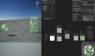
This tutorial covers the creation of a shader in Unity’s Shader Graph which covers the surface of an object with a glowy, plasma-like effect. Further in the tutorial they cover how to make the less pronounced parts of the effect actually completely transparent, which gives a cool effect on its own, or allows for this to be placed over other effects or surfaces to apply the effect with gaps showing the surface below.

Fig. 1: My Results of the Energy Shader Along with Shader Graph View

Quick Notes

HDR Color and Emission

It starts with HDR color with significant intensity into Emission to create glowing, radiant effective.

Voronoi Noise in Layers

Use Voronoi noise to create moving globules effect within the energy. Contrast node used with this to create more distinct dots.

They then created two Voronoi noises with differet cell densities and blended them with a Blend node, giving a combination of tiny particles moving with some larger effects moving throughout the material.

Transparency and Alpha Clip Threshold

By making the Surface of the Graph Inspector Transparent, feeding the Blend result into the now present Alpha on the Fragment node, and setting a proper Alpha Clip Threshold (0.1 is usually a good start), then you can get an effect where parts of the energy shader are totally transparent and see through.

Summary

This tutorial helped me make a simple, yet effective energy effect shader that works decently well on multiple surfaces. The extra segment on including transparency into the effect really took it up a level for me as an interesting effect that could have a lot of uses. This would help expand the effect a bit by also giving it the option of being used on a larger mesh outside of an object’s actual mesh to provide a sort of aura off of and around an object that could be cool, as well as allowing for layering with other effects easier.

They also covered a small segment on using the Gradient node for some strange effects. This was a small segment that also didn’t appeal to me particularly so I didn’t try that portion out myself. That could give some more variety to the tool, but it just wasn’t something I wanted currently.

My result can be seen in action below with a few variations in speed of the effect and color!

via Blogger http://stevelilleyschool.blogspot.com/2021/08/unity-shader-graph-energy-shader-by.html
Unity Shader Graph – Black Hole VFX – by Gabriel Prod.

July 7, 2021

Shader Graph

Unity


Title:
Unity VFX & Shader Graph – Black Hole Effect Tutorial

By:
Gabriel Aguiar Prod.


Youtube – Tutorial #1

Description:
Tutorial for a black hole VFX using Unity’s Shader Graph, particle systems, and Visual Effect graph.


Title:
{ How to CHANGE the SKYBOX in Unity } – HDR Textures in the description

By:

GameDevTraum


Youtube – Tutorial #2

Description:
Quick tutorial to use texture as Skybox in Unity.


General Notes

Fixing Errors

I immediately ran into an issue with the Scene Color node. The fix for this was going to the Main Camera and setting the “Opaque Texture” to ON (found under the Rendering section of the Camera). This made the shader and material match the scene color appropriately, giving that transparent look.

I found a generic space texture to use for my background to emulate the one used in the tutorial. I turned it into a Cube texture to create a Cubemap material to use as my Skybox material. That was what I used Tutorial #2 linked to above for.

I was still having an issue seeing the effects in the scene view (it was just remaining as a matte gray plane). I found that modifying the Opaque Texture flag in the UniversalRenderPipelineAsset (High-Quality for me and my current Unity version) resolved this issue, as described here:


Unity Questions – scene color node not working in shader graph

Multiply to Control Effect Distribution

They multiplied the noise with a round particle texture to create a round visual effect on the rectangular plane that contained all the interesting visual effects. The white parts of the texture contained the focus on the noise, while the black parts did not receive impact from the noise. The transition between the two then also creates a bit of a smoother transition from where the distortion occurs to the lack of distortion.


My Resulting Black Hole VFX from Following Tutorial #1


My Resulting Shader Graph for the Heat Distortion Following Tutorial #1


My Resulting Visual Effect Graph for the Floating Particles Following Tutorial #1

via Blogger http://stevelilleyschool.blogspot.com/2021/07/unity-shader-graph-black-hole-vfx-by.html

Unity Shader Graph – Signed Distance Fields – Update with Subgraph Fix

June 24, 2021

Shader Graph

Unity


Title:
Drawing Boxes and Rectangles in URP Shader Graph with 2D SDFs! 2021.1 | Unity Game Dev Tutorial

By:
Ned Makes Games


Youtube – Tutorial

Description:
Exploration into calculating signed distance fields and using them with Unity’s Shader Graph.


Title:
Rectangle SDFs and Procedural Bricks! Video Production Stream | Unity Game Dev Livestream

By:
Ned Makes Games 2


Youtube – Tutorial

Description:
The full stream which most of the previous tutorial is pulled from. Useful for any more in depth questions of previous tutorial.


Overview

When I visited this tutorial yesterday I ran into an issue with Unity 2021.1.3 that working with subgraphs was extremely bugged and error prone. I had seen online that later versions potentially fixed the issue, so I download the latest version, 2021.1.12, and this did indeed fix the issue for me, making this tutorial much easier to follow along with.

This tutorial was mostly just looking at the subgraphs and shader graphs they built and following along to build them out myself. This was at least a decent learning experience at getting familiar with the work flow of setting up subgraphs for your shader graphs, as well as just using a lot of the math nodes.

Helper Scripts to Show Off Shader

Along with building the shader, they made two simple scripts to make the shader a bit interactive and more flexible.

SetPoints

This class was responsible for letting the user move the two points dictating the general length of the rectangle shape by just clicking and dragging. This however did not work immediately, as they were using a helper class named MousePointer I did not use.

I was able to get a similar result by replacing their process of getting the point:


var p = MousePointer.GetWorldPosition(Camera.main);


with my replacement:


var p = Camera.main.ScreenToWorldPoint(new Vector3(Input.mousePosition.x, Input.mousePosition.y, distanceToPlane));

distanceToPlane was a value the user could put in that is the distance from the camera to the flat plane the camera is facing to test the shader. As long as the exact same distance is put there for the z-value of ScreenToWorldPoint, the points moving correlate exactly with where the user is dragging them.

RectangleThicknessByScrollWheel

This class lets the user control the thickness, or width, of the rectangle with the scroll wheel. This class directly worked as shown.

General Notes with Scripts Interacting with ShaderGraph Properties

Integrating the scripts with the Shader Graph properties was actually pretty easy. It worked similarly to working with the Animator in Unity. You just use methods like SetFloat() and give it two parameters where one is the exact string name of the property you want to set, and the second is the value you are passing in to said property. It is worth noting this was just accessed through the Material, there was no strange Shader Graph object that needed to exist or anything like that.

An example of my implementation of the tutorial can be seen below.


Unity Shader Graph: SDF Rainbow Pulse from Tutorial by NedMakesGames from Steve Lilley on Vimeo.

Video Example of my Following of the Pulse Shader in the Ned Makes Games Tutorial

via Blogger http://stevelilleyschool.blogspot.com/2021/06/unity-shader-graph-signed-distance_24.html

Unity Shader Graph – Signed Distance Fields and Subgraph Errors

June 23, 2021

Shader Graph

Unity


Title:
Drawing Boxes and Rectangles in URP Shader Graph with 2D SDFs! 2021.1 | Unity Game Dev Tutorial

By:
Ned Makes Games


Youtube – Tutorial

Description:
Exploration into calculating signed distance fields and using them with Unity’s Shader Graph.


Overview

This shader tutorial quickly explores calculating signed distance fields and using that for interesting effects. These effects were built in HLSL in the tutorial video originally, but they also show how these can be implemented with Unity’s Shader Graph system. I wanted to use the Shader Graph approach, but unfortunately I found that Unity’s Shader Graph Subgraphs have some major issues.

Signed Distance Fields (SDFs)

Signed Distance Fields (SDFs): calculate the distance from any arbitrary point to a specific shape

Principles of Calculating

To start, they look at an example using a rectangle whose center is at the origin (0, 0).

First, they find the distance from the point, p, to the center of the rectangle, which is just the length of the Vector2 p because the center is at the origin.

Then, using the symmetry of the rectangle, the absolute value of point, p, and the half dimensions of the rectangle are used to determine the distance of the point to any corner of the rectangle.

To get the positive results, they find the vector between the absolute value of point, p, and the corner of the rectangle and find the length of this vector after converting any negative components to 0.

Since the core of an SDF is that it is signed, meaning that a point inside the shape returns a negative value and a point outside the shape returns a positive value, they expand it to deal with negative distances. The vector, d, which is that from the absolute value of point, p, to the corner of the rectangle is only inside of the shape when both components of d are negative.

Assuming both components of d are negative, the result from the previous step already results in 0, so they can add a secondary component to this that returns a negative result in this case. By using min(max(d.x, d.y), 0) they can find this distance because a point within the rectangle must be closer to one wall or the other, or they are identical values. This is why there also is no rounded effect within the rectangle.

Moving the rectangle’s center from the origin just requires an additional offset argument.

Then, rotation requires another argument, and requires rotational matrix math (something I covered in my investigation to changing vector spaces).

Unity Problem with Subgraphs

While following along to mimic their Shader Graphs, I came across a Unity issue working in Sub Graphs especially. When creating properties and moving those property nodes around, Unity consistently runs in ArgumentNullException errors which completely shut the graph down and prevent any further progress until it is closed and reopened. Apparently Unity versions 2021.2 and up may work better with this, so I will have to look into more Unity versions in the future.

via Blogger http://stevelilleyschool.blogspot.com/2021/06/unity-shader-graph-signed-distance.html

Unity Shader Graph – Liquid Effect by Gabriel Aguiar Prod.

June 18, 2021

Shader Graph

Unity


Title:
Unity Shader Graph – Liquid Effect Tutorial

By:
Gabriel Aguiar Prod.


Youtube – Tutorial

Description:
Quick shader graph tutorial exploring interesting effects of moving shader based on psuedo-physics.


Overview

This shader tutorial looked like a great way to extend my knowledge on Unity’s shader graph since it appears to have some neat and unique mechanics. The fact that the shader is responding to the changes in position and rotation of the object explore ways to have shaders follow physics-like rules to create effects visually that can mimic for physical phenomena. Many of this user’s tutorials also include setting up the initial models, but I think this effect can work decently with other simple shapes I can easily make with ProBuilder.

via Blogger http://stevelilleyschool.blogspot.com/2021/06/unity-shader-graph-liquid-effect-by.html

Intro to Unity’s Shader Graph

September 13, 2019

Unity Shader Graph

Intro Tutorial

Youtube – Basics of Shader Graph – Unity Tutorial

Tutorial #1

By: Brackeys


This tutorial introduces you to Unity’s shader graph, so it starts with the bare minimum and goes over some simple features to get you started. Messing with vertex colors got me back into shaders in Unity, and shader graphs provide a really simple way to get some interesting visual effects when I need a break from trying to figure out shader coding.

I already ran into a lot of snags that kept things from working initially. I missed the step at the beginning of the tutorial where they change the Unity project template to Lightweight RP as they’re creating the project. I was able to get around this by doing what they did in their vertex color tutorial, where I created a Lightweight Renderer Pipeline Asset and dragged that into the Graphics tab of the Project Settings.

I then found out that Unity does not like it when you change the name of a shader. I expected this as a possible issue since scripts need to have some of the coding changed to have the class name match the file name, so this seemed like it could be a similar problem. Since the material/shader still was not working, I simply deleted the shader and made a new one with the proper name and everything was finally displaying as a non-error material.

The general effect they were going for was a glowing effect, so they started with using a Fresnel Effect node in the shader graph. This exactly produces a bit of a glowing effect, with a power value that controls how glowy the material is. We then explored applying colors to node effects like this one. This is done by creating a color node, and multiplying it together with the node you intend to color.

There is an interesting feature in the shader graph that actually lets you open the code and see what it is actually doing behind the scenes. This could be useful for exploring the actual shader code behind the vertex color node I was interested in checking out.

Initially, everything is only controllable within the shader graph, with no way to edit anything directly in the Unity Inspector. You can change this however by right clicking in a node and selecting “Convert to Property”. You can still edit it within the shader graph, but it is now found in the Black Board. This does also show the property in your material so you can have different colored/effected objects using the same base shader graph object.

Finally, they just quickly show that the shader graph can accept and apply textures as well. They just do a simple occlusion example to show this off.

My Final Example Following Tutorial

Vimeo – See Animated Shader

Model: Free Asset from Polygonal Series by Meshtint

PROBLEMS

The shader graph was a bit finicky for me and had weird issues. Some of the previews within the shader graph did not appear for me. I tried ] changing up the graph and opening/closing the shader but they remained gone. I will have to try making a project with a Lightweight RP template from the initial setup to see if that changes any settings that impact this.

Once I promoted the color node to a property, it was hard to actually control the final color on the actual object. Sometimes I would change the color in the Blackboard and it would be reflected on the object, then sometimes it wouldn’t. Then editing the color within the created property on the material would only sometimes change the color. I have not found exactly when it passes the reference from being editable in the shader graph to when it is editable in the material (to sometimes not editable at all), but reapplying the material did seem to fix these issues sometimes.

NEXT STEP

More shader graph tutorials would be nice to check out just to get a basic grasp of how to use it to get some nice effects pretty quickly, although I’d still like to look into the coding of shaders as well. I would also be interested in looking how to tie them together, and control some of the parameters of the shader graph through script.

Brackeys Tutorials: Terrain Generation and Vertex Colors (Cont.)

September 12, 2019

Graphics Tutorials

Mesh Generation/Alteration and Vertex Colors

Youtube – MESH GENERATION in Unity – Basics

Tutorial #1

By: Brackeys


Youtube – PROCEDURAL TERRAIN in Unity! – Mesh Generation

Tutorial #2

By: Brackeys


Youtube – MESH COLOR in Unity – Terrain Generation

Tutorial #3

By: Brackeys


Tutorial #3

Tutorial #3 actually covers UVs and applying textures to surfaces, as well as vertex colors and shaders in Unity. It starts by covering UVs and applying textures, and the main take away is that you want to normalize your UV vectors so they are within the range of [0, 1]. Textures are applied in a normalized fashion when dealing with UVs.

It then gets into setting the vertex colors. This is done by creating a Color array and then simply setting the Mesh.colors of the mesh equal to that array. We created a colors array that was the same size as our vertices, which leads me to believe that a mesh colors array generally has the same number of indices as vertices.

To set the colors, the underlying concept is that the color should correspond to the height of a vertex. This requires some more normalization, which requires us to keep track of the minimum and maximum terrain heights, so that we can use these as our bounds for a [0, 1] range. This is important because we are coloring with a Gradient. Unity has a method that goes with Color and Gradient called Gradient.Evaluate(), which can take in a value between [0, 1] and assign a color based on the given gradient (0 being one end of the color gradient, 1 being the other, and numbers in between being the middle colors or blends).

Once we’ve created the Color array and applied it to our mesh, it does not yet display. This is because most general Unity shaders don’t show this effect. To resolve this, they used Unity’s shader graph to apply the vertex colors to the surface’s actual colors. Using this requires the installation of the Lightweight Render Pipeline and the Shader Graph. You had to create a Lightweight Render Pipeline Asset and drag that into the Graphics section of your Project Settings for reasons that are not explained. You then create a shader with the option of “PBR Graph” to make your shader using the visual node system of the Shader graph. Once there, we just simply added a Vertex Color node and dragged that into the Albedo value of our material to apply the vertex colors.

Example Generated Terrain with Vertex Colors – by me

FURTHER TESTING

I wanted to experiment a bit more with this to see how applying it to some existing meshes could possibly work. I started simple by just using a basic Unity cube. I made a quick script for it that just grabbed a reference to its mesh and went through its entire mesh.vertices array to check exactly how many there were, and there were 24 as I expected {the 8 corners each have 3 vertices, dealing with the 3 different normals of the 3 intersecting faces). I then just made a few public Color options that could be fed into a small 3 color array that would be distributed to vertices around the cube. I applied my material with the created shader, and sure enough, this created the various vertex color effects around my cube.

Here is the script breakdown for this small test: public class CubeVertexColor : MonoBehaviour
{
Mesh mesh;
int vertexCounter = 0;

public Color color1;
public Color color2;
public Color color3;

private Color[] colorArray;
private Color[] vertexColors;

private void Start()
{
mesh = GetComponent().mesh;

colorArray = new Color[] { color1, color2, color3 };
vertexColors = new Color[24];

for(int i = 0; i < mesh.vertices.Length; i++)
{
vertexColors[i] = colorArray[i % 3];
Debug.Log(“The name of this vertex is: ” + mesh.vertices[i]);
vertexCounter = i + 1;
}

mesh.colors = vertexColors;

Debug.Log($”There are {vertexCounter} vertices in the cube mesh.”);
}
}

Example Cube with Vertex Colors – by me

NEXT STEP

I would still like to look into an actual shader script that is able to give similar results for vertex colors. I have gathered some resources today that I will most likely make a post with. I was hoping this could be a helpful tool for creating objects within Unity, but it still seems like it will be easier to make them outside and apply the vertex colors with another software. This will still be helpful in actually displaying those colors though if that is the route I take.

General Graphics in Unity – Vertex Colors, Shaders, Meshes, UVs

September 11, 2019

General Graphics Information

Meshes, Shaders, Vertices, UVs

Youtube – MESH COLOR in Unity – Terrain Generation

Tutorial #1

Youtube – Learning Shaders in Unity – Everything about Meshes in under 5 Minutes

Info #1

Youtube – Pico Tanks: Vertex shader in Unity

Info #2

Tutorial #1

I was interested at looking into using vertex colors for objects, which led me to a few interesting videos on various aspects of 3D modeling in general. Tutorial #1 was a nice example of using vertex colors in Unity, as well as giving me a simple tutorial to look into on mesh deformation as well. It uses Unity’s shader graph to apply vertex colors, and just simply sets colors with a gradient onto the vertices themselves based on their height (y position).

Info #1

Info #1 was a very brief but general overview of topics on meshes.

  • UVs: It explained how UVs are used to map textures onto faces of objects, which was the biggest topic I had not really covered up to this point. UVs also belong directly to a vertex.
  • Vertices: It also went into how their can be more vertices on an object than you’d expect (since they have a normal that goes with individual faces).

This video was specifically aimed at Unity, so some of the information was most likely Unity specific. For instance, the fact that the Mesh class contains Vertices, Normals, UVs, Tangents, Triangles, and Colors. It finally got into vertex colors at the end, which also showed an example of it being used that just made a very cool colored cube I thought.

From: Info #1

Info #2

Finally, Info #2 was just a very quick video of a game project showcasing their use of vertex shaders to actually move trees in their environment when objects are moving through them. Moving objects affect the colors of an underlying texture map, which use this “color information” to apply affects, such as rotating the trees.

Starting with Unity Shader Graphs – Brackeys

May 12, 2019

Unity Shader Graphs

Basic Tutorials

Youtube – MY NEW FAVOURITE FEATURE! – Shader Graph Tutorial

By: Brackeys

Youtube – FORCE FIELD in Unity – SHADER GRAPH

By: Brackeys

These tutorials get into the basics of using the Shader Graph feature in Unity. This seems like a nice tool to have a basic understanding of to make some cool effects, so I want to check in on it at some point.