3D Math – Always a Single Plane to Cut Three 3D Objects in Half with Borsuk-Ulam Theorem – by Zach Star

June 28, 2021

Borsuk-Ulam Theorem

3D Math


Title:
A surprising topological proof – Why you can always cut three objects in half with a single plane

By:
Zach Star


Youtube – Information

Description:
Proving that any set of n n-dimensional objects can be cut in half by n-1 dimensional object (i.e. 3 3D objects can be cut in half by a 2D plane).


Overview

This was just a fun and interesting mathematical proof I came across. Using the Borsuk-Ulam Theorem at its core, it proves how any set of 3 3D objects can be cut in half (by volume) by some 2D plane. It then expands that to show that this works for any n amount of n-dimensional objects, which are then divided by an object with n-1 dimensions.

Borsuk-Ulam Theorem

This can be read up on here at the corresponding wikipedia page:

Wikipedia – Borsuk-Ulam Theorem

This states: “every continuous function from an n-sphere into Euclidean n-space maps some pair of antipodal points to the same point”. The simple explanations they use to show how it is used is that in the 2D case, there must exist at least 2 points around the equator with the same temperature, and in the 3D case, there must exist at least 2 points in the entirety of Earth that have the same temperature and pressure. Another key note is this is only true assuming all parameters vary continuously in space.

Expanding to Proof on Dividing Objects

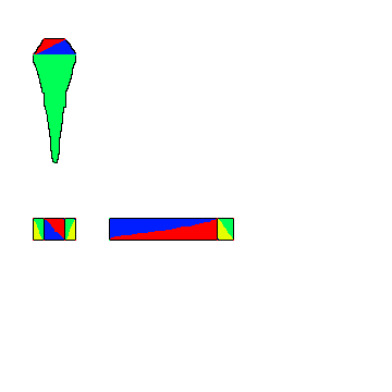
To apply this to the concept they were investigating, they start with the 2D example since it is easier to visualize, and will eventually lead to the same foundational concepts used for any n-dimensional case. They begin with a unit circle, and show how the tangent to every point around the circle accounts for every possible slope in this space and how any of those lines can be used to cut any shape in half by area.

The key to using the Borsuk-Ulam Theorem in this case is that they need to assign a value to that point on the circle. To do so, they use the distance between the two parallel lines that are cutting the two shapes in half. Because they want to find antipodal points which are equivalent, they create a signed distance system. The sign of the distance is based on the normal of the point on the unit circle. If that normal points towards shape #1, it is positive, and if it points towards shape #2, it is negative. They do this because there is only one case where the positive and opposite of a value is equal, and that’s when it is 0. This proves that the 0 value will exist, and a distance of 0 between the two lines indicates they are the same line cutting both shapes in half.

Summary

Honestly I was mostly just interested in the concept that there’s always at least 1 plane that can cut up to 3 3D objects in half, and was not fully connecting the dots on all the steps through the process for actually proving this to be true. Just learning about the Borsuk-Ulam Theorem in itself was very interesting, and seeing some of the unexpected cases it can be used to help prove was pretty eye opening. I did want to check it out because I thought it would be a fun concept to explore with a small Unity project to create a puzzle-like game centered around this concept, while also providing some background information on some of these concepts and theorems.

via Blogger http://stevelilleyschool.blogspot.com/2021/06/3d-math-always-single-plane-to-cut.html

Unity Shader Graph – Signed Distance Fields – Update with Subgraph Fix

June 24, 2021

Shader Graph

Unity


Title:
Drawing Boxes and Rectangles in URP Shader Graph with 2D SDFs! 2021.1 | Unity Game Dev Tutorial

By:
Ned Makes Games


Youtube – Tutorial

Description:
Exploration into calculating signed distance fields and using them with Unity’s Shader Graph.


Title:
Rectangle SDFs and Procedural Bricks! Video Production Stream | Unity Game Dev Livestream

By:
Ned Makes Games 2


Youtube – Tutorial

Description:
The full stream which most of the previous tutorial is pulled from. Useful for any more in depth questions of previous tutorial.


Overview

When I visited this tutorial yesterday I ran into an issue with Unity 2021.1.3 that working with subgraphs was extremely bugged and error prone. I had seen online that later versions potentially fixed the issue, so I download the latest version, 2021.1.12, and this did indeed fix the issue for me, making this tutorial much easier to follow along with.

This tutorial was mostly just looking at the subgraphs and shader graphs they built and following along to build them out myself. This was at least a decent learning experience at getting familiar with the work flow of setting up subgraphs for your shader graphs, as well as just using a lot of the math nodes.

Helper Scripts to Show Off Shader

Along with building the shader, they made two simple scripts to make the shader a bit interactive and more flexible.

SetPoints

This class was responsible for letting the user move the two points dictating the general length of the rectangle shape by just clicking and dragging. This however did not work immediately, as they were using a helper class named MousePointer I did not use.

I was able to get a similar result by replacing their process of getting the point:


var p = MousePointer.GetWorldPosition(Camera.main);


with my replacement:


var p = Camera.main.ScreenToWorldPoint(new Vector3(Input.mousePosition.x, Input.mousePosition.y, distanceToPlane));

distanceToPlane was a value the user could put in that is the distance from the camera to the flat plane the camera is facing to test the shader. As long as the exact same distance is put there for the z-value of ScreenToWorldPoint, the points moving correlate exactly with where the user is dragging them.

RectangleThicknessByScrollWheel

This class lets the user control the thickness, or width, of the rectangle with the scroll wheel. This class directly worked as shown.

General Notes with Scripts Interacting with ShaderGraph Properties

Integrating the scripts with the Shader Graph properties was actually pretty easy. It worked similarly to working with the Animator in Unity. You just use methods like SetFloat() and give it two parameters where one is the exact string name of the property you want to set, and the second is the value you are passing in to said property. It is worth noting this was just accessed through the Material, there was no strange Shader Graph object that needed to exist or anything like that.

An example of my implementation of the tutorial can be seen below.


Unity Shader Graph: SDF Rainbow Pulse from Tutorial by NedMakesGames from Steve Lilley on Vimeo.

Video Example of my Following of the Pulse Shader in the Ned Makes Games Tutorial

via Blogger http://stevelilleyschool.blogspot.com/2021/06/unity-shader-graph-signed-distance_24.html

Unity Shader Graph – Signed Distance Fields and Subgraph Errors

June 23, 2021

Shader Graph

Unity


Title:
Drawing Boxes and Rectangles in URP Shader Graph with 2D SDFs! 2021.1 | Unity Game Dev Tutorial

By:
Ned Makes Games


Youtube – Tutorial

Description:
Exploration into calculating signed distance fields and using them with Unity’s Shader Graph.


Overview

This shader tutorial quickly explores calculating signed distance fields and using that for interesting effects. These effects were built in HLSL in the tutorial video originally, but they also show how these can be implemented with Unity’s Shader Graph system. I wanted to use the Shader Graph approach, but unfortunately I found that Unity’s Shader Graph Subgraphs have some major issues.

Signed Distance Fields (SDFs)

Signed Distance Fields (SDFs): calculate the distance from any arbitrary point to a specific shape

Principles of Calculating

To start, they look at an example using a rectangle whose center is at the origin (0, 0).

First, they find the distance from the point, p, to the center of the rectangle, which is just the length of the Vector2 p because the center is at the origin.

Then, using the symmetry of the rectangle, the absolute value of point, p, and the half dimensions of the rectangle are used to determine the distance of the point to any corner of the rectangle.

To get the positive results, they find the vector between the absolute value of point, p, and the corner of the rectangle and find the length of this vector after converting any negative components to 0.

Since the core of an SDF is that it is signed, meaning that a point inside the shape returns a negative value and a point outside the shape returns a positive value, they expand it to deal with negative distances. The vector, d, which is that from the absolute value of point, p, to the corner of the rectangle is only inside of the shape when both components of d are negative.

Assuming both components of d are negative, the result from the previous step already results in 0, so they can add a secondary component to this that returns a negative result in this case. By using min(max(d.x, d.y), 0) they can find this distance because a point within the rectangle must be closer to one wall or the other, or they are identical values. This is why there also is no rounded effect within the rectangle.

Moving the rectangle’s center from the origin just requires an additional offset argument.

Then, rotation requires another argument, and requires rotational matrix math (something I covered in my investigation to changing vector spaces).

Unity Problem with Subgraphs

While following along to mimic their Shader Graphs, I came across a Unity issue working in Sub Graphs especially. When creating properties and moving those property nodes around, Unity consistently runs in ArgumentNullException errors which completely shut the graph down and prevent any further progress until it is closed and reopened. Apparently Unity versions 2021.2 and up may work better with this, so I will have to look into more Unity versions in the future.

via Blogger http://stevelilleyschool.blogspot.com/2021/06/unity-shader-graph-signed-distance.html

Lerp Fundamentals in Unity

May 10, 2021

Lerp

Unity


Title:
How to Use Lerp (Unity Tutorial)

By:
Ketra Games


Youtube – Tutorial

Description:
A brief coverage of exactly how Lerp works in Unity with a couple ways to use it.


Overview

I was recently researching ways to effectively use Lerp in Unity and came across some strange implementations that made me unsure if I understood how it worked. This video however specifically covered that case and explained that it does work, but it’s not a particularly ideal solution.

The case covered is specifically called the “Incorrect Usage” in this video. It is when Time.deltaTime alone is entered as the time parameter for Lerp. As I thought, this is just entering some tiny number as a time parameter each time it is called, which is then used to just some value between the intial and final values entered into the Lerp. It is not very controlled, and it leads to a strange situation where it keeps getting called and updated but it does not theoretically reach the final position ever (although this may be different with how computers handle the values eventually).

Finally they cover a couple time parameters to use with Lerp to get a few varied results. SmoothStep is one they suggest to get a result similar to the “Incorrect Usage” but done properly. It adds a bit of a slowing effect as the value gets closer to the final result. They also show using an Animation Curve to control the value in many various mathematical ways over time.

via Blogger http://stevelilleyschool.blogspot.com/2021/05/lerp-fundamentals-in-unity.html

Game Project: Flying Game – Part 2 – 3D UI Guide with Rotational Matrices

May 4, 2021

Flying Game

UI & Matrix Rotations


Overview

I wanted to make a 3D UI element which could direct the player in open flying space towards a point of interest or goal. This needed to point towards the object positionally, as well as account for the rotation or direction the player is facing. This makes sure that no matter where they are and what direction they are facing, it can guide them to turn the proper direction and make informed decisions to move directly towards that goal.

After deciding that changing my frame of reference could be a solution for this problem, I found Unity’s InverseTransformDirection method which can change a Vector from one space to another. To make sure this was providing a result similar to what I expected mathematically, I also wrote out the math for performing a matrix rotation on the vector and was happy to see it gave the same results.

3D UI Element – Real Time Guide Towards Goal

Add a 3D Element to the Unity Canvas

You change the render mode of the Canvas to Screen Space – Camera, which requires adding a Camera reference. To satisfy this, create another Camera separate from the main with the above settings. Drag this Camera in as the reference for your Canvas. Now 3D objects can be added to the Canvas.

Make sure the 3D elements added are on the UI layer. Sometimes the scaling can be strange, so you may need to scale the objects up substantially to see them on the Canvas. Also your main Camera may separately render the object as well, so to avoid this remove the UI layer from the Culling Mask for your main Camera.

    Canvas Settings:

  • Render Mode = Screen Space – Camera
  • Render Camera = Created UI Camera
    UI Camera Settings:

  • Clear Flags = Depth only
  • Culling Mask = UI
  • Projection = Orthographic

Unity’s InverseTransformDirection to Set Guide Upward Ray

Using Unity’s “InverseTransformDirection()” method from the player’s transform with the vector pointing from the player’s position to the intended goal allowed me to change the frame of reference of the goal vector from world space to that of the player. This properly rotates the vector to associate itself with the player’s current rotation as well as their position relative to the goal.

Creating my Own Rotational Transformation on the Goal Vector to Compare to Unity’s InverseTransformDirection

To double check what this was doing, I found the math to change the frame of reference of a vector from one frame to another at the link attached. Since the player currently only rotates on a single axis (the y-axis in this case), I could directly copy the example seen in the video which investigates representing a vector in a new frame with a rotation about a single axis (to keep the terms simpler for now). Following this math I got the exact same results as Unity’s InverseTransformDirection method, indicating they perform the same operations.

Creates Vector from Player to Goal

private Vector3 PointTowardsGoal()
{
	return goal.position - player.transform.position;
}

Transforms Goal Vector from World Space to Player’s Space with Unity InverseTransformDirection

private Vector3 PointTowardsGoalRelativeToForward()
{
	// Translate direction to player's local space
	relativeDirectionFromForwardToGoal = player.transform.InverseTransformDirection(PointTowardsGoal());

	return relativeDirectionFromForwardToGoal;
}

Transforms Goal Vector from World Space to Player’s Space with Rotation Matrix Math

private Vector3 GoalVectorInFrameOfPlayer()
{
	// pr
	Vector3 originalVector = PointTowardsGoal();

	// Obtain rotation value (in radians); Rotation angle about the y-axis
	float theta = player.transform.localRotation.eulerAngles.y * Mathf.PI / 180;

	// p1
	Vector3 vectorInNewFrame = new Vector3(
		originalVector.x * Mathf.Cos(theta) - originalVector.z * Mathf.Sin(theta),
		originalVector.y,
		originalVector.x * Mathf.Sin(theta) + originalVector.z * Mathf.Cos(theta)
		);
		
	return vectorInNewFrame;
}


Flying Game Project: 3D UI Guide Towards Goal Prototype from Steve Lilley on Vimeo.

Video 1: Prototype of 3D UI Guide Using Unity InverseTransformDirection


Flying Game Project: Comparing Unity's InverseTransformDirection to my Own Rotational Matrices from Steve Lilley on Vimeo.

Video 2: Update Using Rotational Matrix Math on Goal Vector

Summary

It is good to know that for standard procedures where I want to change the relative frame of a vector that Unity’s InverseTransformDirection() method appears to do that. As showcased here, that can be a very strong tool when you need to translate vector information from your game’s world space to an element in your UI, whether that be through the player’s current frame reference or something else.

Learning how to setup a Canvas to use 3D assets in your UI is also good to know just to increase the flexibility of options you have when creating a UI. Some information can be difficult to convey with a 2D tool, so having that option can open avenues of clarity.

via Blogger http://stevelilleyschool.blogspot.com/2021/05/game-project-flying-game-part-2-3d-ui.html

Coding Adventure: Ray Marching by Sebastian Lague

April 12, 2021

Ray Marching

Unity


Title:
Coding Adventure: Ray Marching


By: Sebastian Lague


Youtube – Tutorial

Description:
Introduction to the concept of ray marching with some open available projects.


Overview

This video covers some of the basics of ray marching while also visualizing their approach and creating some interesting visual effects and renders with the math of signed distance along with ray marching logic. The major ray marching method they show is sphere tracing, which radiates circles/spheres out from a point until anything is collided with. Then, the point moves along the ray direction until it reaches the radius of that sphere projection and emits another sphere. This process is repeated until it radiates a very small threshold radius sphere, which is when a collision is determined.

The resulting project made is available, and I think it would be very useful and interesting to explore. The Youtube video description also holds many links to various sources used to create all the tools and effects in the video, which could also be beneficial for further research into these topics.

Fig. 1: Example of Raytracing Visual from Video (by Sebastian Lague)

via Blogger http://stevelilleyschool.blogspot.com/2021/04/coding-adventure-ray-marching-by.html

Linear Algebra and Vector Math – Basics and Dot Product – by Looking Glass Universe

April 8, 2021

Linear Algebra

Vectors and Dot Product


Title:
Vector addition and basis vectors | Linear algebra makes sense


Youtube – Link #1

Description:
Introduction to this series and the basics of linear algebra and vectors.


Title:
The meaning of the dot product | Linear algebra makes sense


Youtube – Link #2

Description:
Deep dive into the dot product and what it represents and how to determine it.


Overview

I wanted to brush up on my vector math fundamentals, particularly with my understanding of the dot product and its geometric implications as it is something that comes up often in my game development path. While I am able to understand it when reading it and coding it for various projects, I wanted to build a more solid foundational understanding so that I could apply it more appropriately on my own. This video series has been very nice for refreshing my learning on these topics, as well as actually providing me a new way of looking at vector math that I think will really further my understanding in the future.

Video #1 – Vector addition and basis vectors

This was the introductory video to the series, and starts with vector addition. They then move on to linear combinations as an extension of basic vector addition. Next they show for 2D vectors that as long as you have two independent vectors, you can calculate any other vector using those two in some linear combination. This then relates to how vectors are normally written out, but they are simply using linear combinations of the standard orthonormal basis of something like x and y, or x, y, and z in 3D space.

This means a vector is simply 2 or 3 vectors created with the unit vector in the x, y, or z direction multiplied by some scalar and then summed up to create the resulting vector. This was actually a new way for me to look at vectors, as this is more intuitive when you are looking to create a new vector set to base vectors off of different from the standard x, y, z, but I never really thought to also apply it in the standard case. The x, y, z, or even i, j, k, became some standardized to me that I generally ignored them, but I think looking at them in this way will help make much more of linear algebra more consistent in my thinking space.

They then continue on to explain spans, spaces, and the term basis a bit more. A set of vectors can be called a span. If that span is all independent vectors, this indicates it is the smallest amount of vectors which can fully describe a space, and this is known as a basis. The number of basis elements is fixed, and this is the dimension of the space (like 2D or 3D). And for a given basis, any vector can only uniquely be defined in one linear combination of the basis vectors.

Video #2 – The meaning of the dot product

Dot Product

A really simple way of describing the dot product is that it shows “how much one vector is pointing in the same direction of another vector”. If those two vectors are unit vectors, the dot product of two vectors pointing the same direction is 1, two vectors that are perpendicular would have a dot product of 0, and two vectors pointing directly opposite directions would have a dot product of -1. This is directly calculated as the cosine of the angle between the two vectors.

However, the dot product also factors in the magnitude of the two vectors. This is important because it makes the dot product a linear function. This also ends up being more useful when dealing with orthonormal basis vectors, which are unit vectors (vectors of length 1) that define the basis of a space and are all orthogonal to each other.

They cover a question where a vector u is given in the space of the orthonormal vectors v1 (horizontal) and v2 (vertical) and ask to show what the x value of the u vector is (which is the scalar component of the v1 vector part of the linear combination making up the vector u) with the dot product and vectors u and v1. Since v1 is a unit vector, this can be done directly by just the dot product (u . v1). They then show that similarly the y component would just be the dot product (u . v2). They explain this shows the ease of use of using the dot product along with an orthonormal basis, as it directly shows the amount of each basis vector used in the linear combination to create any vector. This can also be explained as “how much of u is pointing in each of the basis directions”.

Since the dot product is linear, performing the dot product function on two vectors is the same whether done directly with those two vectors, or even if you break up one of the vectors before hand into a linear combination of other vectors and distribute it.


Example:

a . b = (x*v1 + y*v2) . b = x*v1 . b + y*v2 . b

Projecting a Vector onto Another Vector

They then cover the example I was very interested in, which is what is the length of the vector resulting in projecting vector A onto vector B in a general sense. The length, or magnitude, of this vector is the dot product divided by the magnitude of vector B. This is similar to the logic in the earlier example showing how vectors project onto an orthonormal basis, but since they had magnitudes of 1 they were effectively canceled out originally.

This then helped me understand to further this information to actually generate the vector which is the projection of vector A onto vector B, you then have to take that one step more by multiplying that result (which is a scalar) with the unit vector of B to get a vector result that factors in the proper direction. This final result ends up being the dot product of A and B, divided by the magnitude of B, then multiplied by the unit vector of B.


Example:

Projection vector C

C = (A . B) * ^B / ||B|| = (A . B) * B / ||B||^2

Dot Product Equations

They have generally stuck with the dot product equation which is:

a . b = ||a|| ||b|| cos (theta)


They finally show the other equation, which is:

a . b = a1b1 + a2b2 + a3b3 + …

But they explain this is a special case which is only true sometimes. It requires that the basis you are using is orthonormal. So this will generally be true in many standard cases, but it is important to note that it does require conditions to be met. This is because the orthonormal basis causes many of the terms to cancel out, giving this clean result.

via Blogger http://stevelilleyschool.blogspot.com/2021/04/linear-algebra-and-vector-math-basics.html

Architecture AI Pathing Project: Upward Raycast for Better Opening Detection

January 11, 2021

Raycast for A* Nodes

Architecture AI Project


Original Downward Raycast and Downfalls

The raycasting system for detecting the environment to setup the base A* pathing nodes was originally using downward raycasts. These rays traveled until they hit the environment, and then set the position of the node as well as whether it is walkable or not. An extra sphere collision check around the point of contact was also conducted so as to check for obstacles right next to the node as well.

This works for rather open environments, but this had a major downside for our particular needs as it failed to detect openings with in walls and primarily doors. Doors are almost always found within a wall, so the raycast system would hit the wall above the door and read as unwalkable. This would leave most doors as unwalkable areas because of the walls above and around them.

Upward Raycast System Approach

Method

The idea of using an upward raycast was that it would help alleviate this issue of making openings within walls unwalkable when they should be walkable. By firing the rays upward, the first object hit in most cases can safely be assumed to be the floor because our system only works with a single level at this time. Upon hitting the first walkable target (in this case, the assumed floor), this point is set and another raycast is fired upward until it hits an unwalkable target. If no target is hit, this is determined as walkable (as there is clearly nothing unwalkable blocking the way), but if a target is hit, the distance between these two contact points is calculated. This distance is then compared with a constant height check and if the distance is greater, the node is still marked as walkable even though it eventually hit an unwalkable object.

This approach attempts to measure the available space between the floor and any unwalkable objects above it. If a wall is set directly onto the floor, as many are, the distance will be very small so it will not meet the conditions and will be set unwalkable appropriately. If there is a walkable door or just a large opening such as an arch, the distance between the floor and the wall above the door or the example arch way should be large enough that the system notes this area is still walkable.

Sphere Collision Check for Obstacles

Similarly to the original system, we still wanted a sphere collision check to help note obstacles very close to nodes so that the obstacles would not slip between the cracks of the rays cast, effectively becoming walkable. We included this similarly, but it is noted because the initial hit used is now below the floor, so the thickness of the floor must be accounted for. Currently a larger radius check is just needed so it can reach above and through the floor. In future edits, it could make sense to have a noted constant floor thickness and perform the sphere radius check above the initial raycast contact point according to this thickness.

Test Results

Details

I compared the two raycast methods with a few areas in our current test project. In the following images, the nodes are visualized with Unity’s cube gizmos. The yellow nodes are “walkable” and the red nodes are “unwalkable”. Most of the large white objects are walls, and the highlighted light blue material objects are the doors being observed.

Test 1

A high density door area was chosen to observe the node results of both systems.

The downward check can work for doors when the ray does not directly hit a wall, as the sphere check properly checks them as walkable from the floor. However, the rays hitting the walls can be seen by the unwalkable nodes placed on top of them. A clear barrier is formed along the entirety of the walls, effectively making the doors unwalkable.

The upwards raycast test clearly shows every door has at least a single node width gap of walkable nodes in every case. The doors that were originally unwalkable with the downward raycast and now walkable as the height check was met.

Test 1: Downward Raycast


Test 1: Upward Raycast

Test 2

A larger room with a single noteable door was observed.

The downward check does pose a problem here as a full line of unwalkable nodes can be seen on the floor blocking access through the door and into the room. Because the problem is seen with nodes on the floor rather than nodes on top of the wall, this is actually a case where the sphere collision check is the problem and not the raycast particularly. Changing the collision radius for the check could potentially solve the issue here.

The upwards raycast is able to cleanly present a walkable path through this door into the room. While this does give us the result we desired, it should be noted again this difference can be attributed to the difference in the sphere collision check for obstacles. The same radius was used for both tests, but the upwards raycast sphere orginates from the bottom of the floor, so the extra distance it has to travel through the floor is what really opens up this path.

Test 2: Downward Raycast


Test 2: Upward Raycast

Summary

The upwards raycast seems extremely promising in providing the results we wanted for openings, doors especially. The tests clearly demonstrate that it helps with a major issue case the downward check had, so it is at worst a significant upgrade to the original approach. The upward raycast with distance check method also succeeded in other door locations, supporting its consistency. It will still have trouble from time to time with very narrow openings, but should work in a majority of cases.

via Blogger http://stevelilleyschool.blogspot.com/2021/01/architecture-ai-pathing-project-upward.html

Dealing with Unity Forces for Statics Game Concept

AddForce – Unity Official Tutorials

Youtube – AddForce – Unity Official Tutorials

The bare basics of scripting forces in Unity with rigidBody’s. The AddForce can take two inputs: a vector for direction and magnitude, and what type of force it is.

ForceModes
  • Acceleration – Continuous change; not affected by mass
  • Force – (Default) Continuous change; affected by mass
  • Impulse – Instant change; affected by mass
  • VelocityChange – Instant change; not affected by mass
AddTorque – Unity Official Tutorials

Youtube – AddTorque – Unity Official Tutorials

The bare basics of scripting torques in Unity with rigidBody’s. The AddTorque can take two inputs: a vector axis to apply torque around, and what type of torque it is. This is very similar to AddForce. Important to remember, Unity uses “LEFT HAND RULE” for rotation.

ForceModes
  • Acceleration – Continuous change; not affected by mass
  • Force – (Default) Continuous change; affected by mass
  • Impulse – Instant change; affected by mass
  • VelocityChange – Instant change; not affected by mass
Game Ideation
Engineering Teaching & Research Equipment – Armfield

EF-1.1 – Statics – Forces experiment kit
Youtube – EF series video Statics Forces 1 1 3

The links are similar videos, the first is just directly to the site of those that made the kit, and the second is a Youtube link. This kit provides hand on experience for understanding a lot of topics based around static equilibrium. Topics such as 2D shape center of masses, force vectors, and much more can be covered with this tool.

Game Idea – Engineering Statics Game

Following the general idea of the kit shown above, the game environment is populated with nodes that apply controllable forces to a central ring object. These forces can be altered to change the position of the ring. The environment will spawn collectibles that the player must direct the ring towards in order to collect them. To move the ring, they will need to intelligently alter the forces applied by the nodes.

Quick sketch of concept
Concept visualization of force body diagram to show how game can function.

DIGM-540 Gear Mesh Generating Resources

  1. Basic Mesh Scripting Tool Description for Unity
  2. Creating Basic Billboard Mesh Through Unity Scripting
    Shows how to create a vertex array, set these into triangles, and create a full mesh.

  3. More Help for Procedural Generation of Mesh

This shows that it is possible to create/modify meshes within Unity using scripting.

Project Direction – Create Script in Unity that Will Take User Inputs to Instantiate a Gear Model Based on Said Parameters

This may be possible through the general use of the Mesh class in Unity scripting. Something along the lines of creating a set of vertices for the central body (some smoothness level of cylinder), then creating a gear tooth mesh that can be multiplied and geometrically positioned around the central core body mesh created.

Bump Mapping

Normal Maps from Unity

“Normal Maps and Height Maps are both types of Bump Map. They both contain data for representing apparent detail on the surface of simpler polygonal meshes, but they each store that data in a different way. A height map is a simple black and white texture, where each pixel represents the amount that point on the surface should appear to be raised. The whiter the pixel colour, the higher the area appears to be raised.

A normal map is an RGB texture, where each pixel represents the difference in direction the surface should appear to be facing, relative to its un-modified surface normal. These textures tend to have a bluey-purple tinge, because of the way the vector is stored in the RGB values.”

Displacement Maps

Unity Displacment Maps and Tesselation

Tri Setup to Create Mesh for Gear Segments
Showing example breakdown of a gear segment in tris.