Architecture AI Pathing Project: Another File Reader for Revit Model Data

December 3, 2020

File Reader

Architecture AI Project


Another File Reader: Revit Model Data

After reconstructing the file reader to read in various coordinate data to be passed on to the A* pathing node grid, we also needed a file reader to read in data from the Revit model itself to reapply that data to the models in Unity. Revit allows the user to apply many parameters and lots of data to the models contained within it, and that data can be exported as a large Excel file. That data however is not being passed into Unity when exported as an .fbx file, so we needed a way to reapply that data using the exported data.

Goal

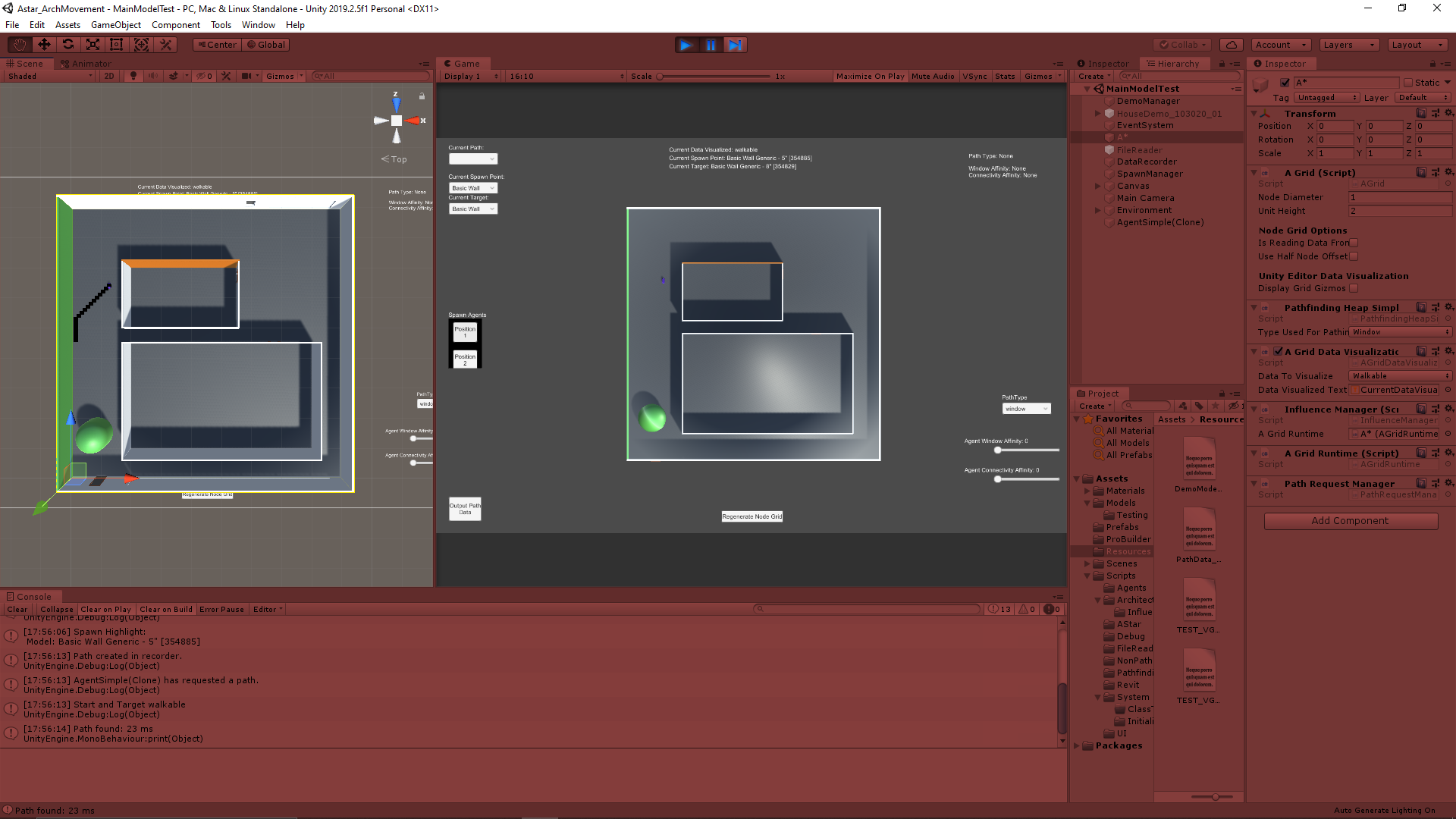
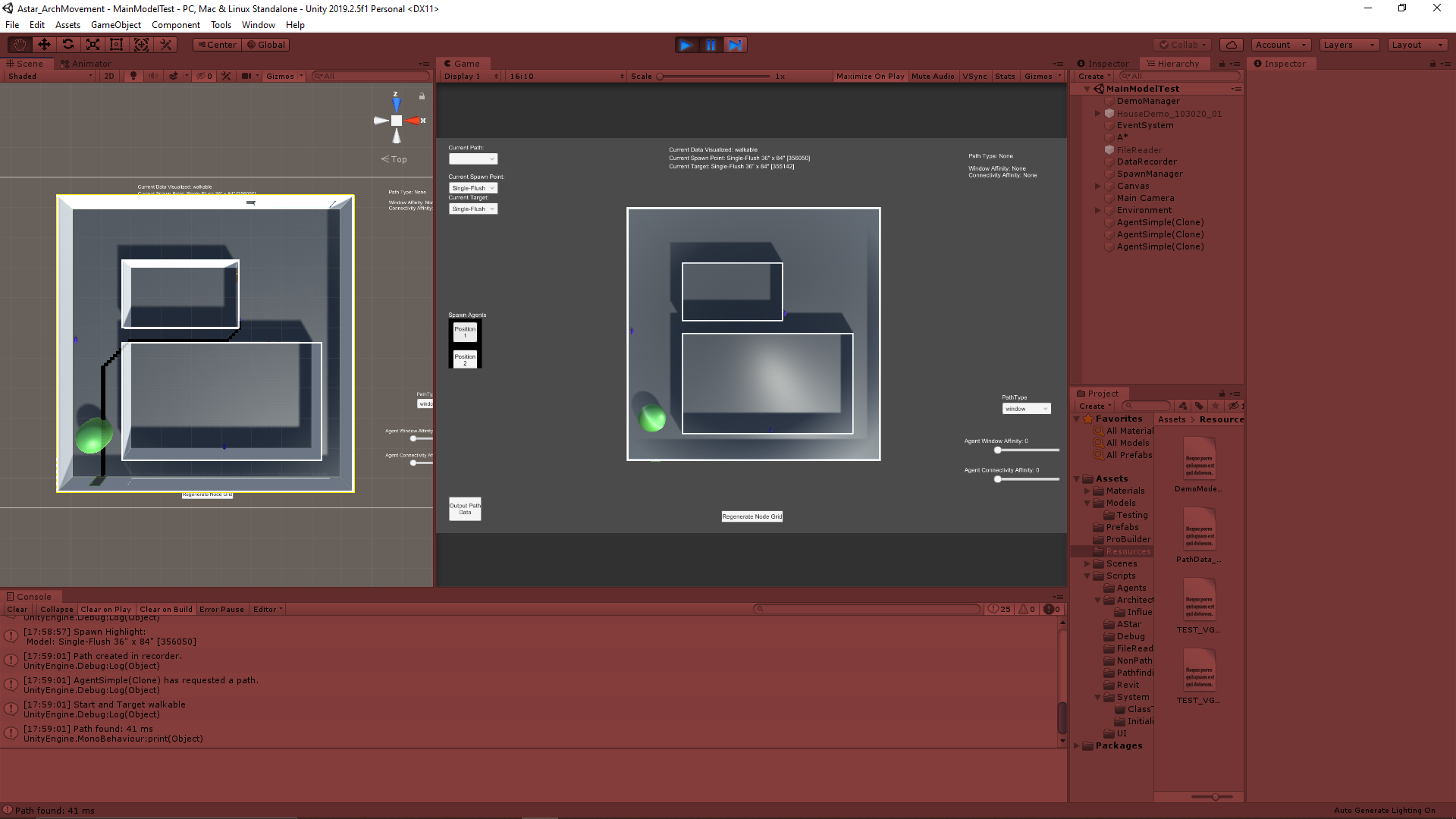
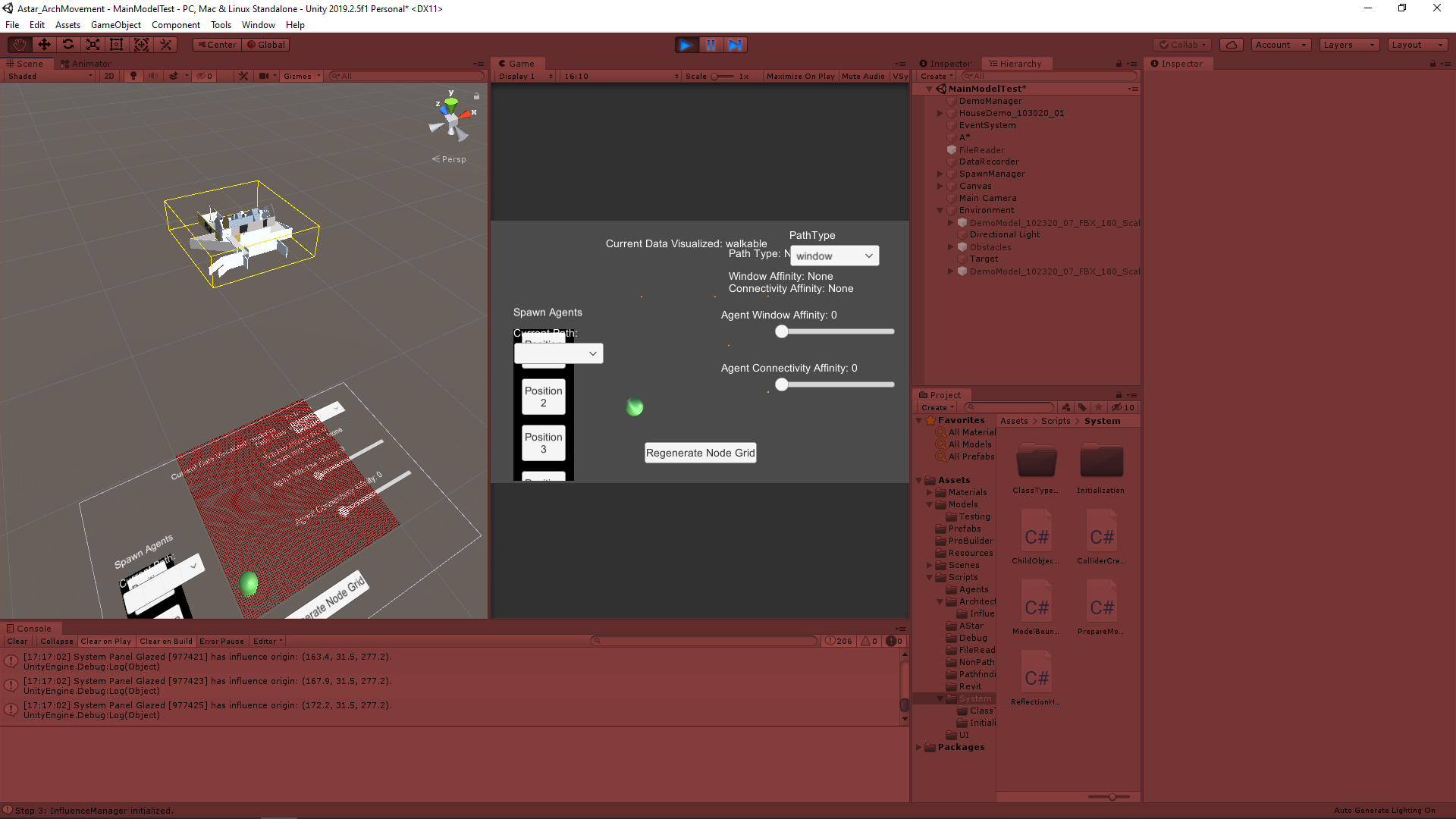
While this is a flexible enough concept to apply many parameters, the main problem this system is being created to solve was automating the process of labeling what parts of the model are “walkable” or “unwalkable”. I had created a system to somewhat help do that in Unity, but this system will allow the user to do that work on the Revit side. They can create a “Walkable” parameter in Revit for specific objects and that information will be passed through Unity back onto the same object in the Unity model. A similar logic is being applied to which doors are passable in the overall model, with a parameter like “isClosed”.

Using the Revit Model Data

As of now, all the exported data is coming out in a large Excel .xlsx file which has dozens and dozens of sheets. These are difficult to innately read directly into Unity, so I investigated mass converting them into .csv files to be consistent with how we are already reading in the other types of data. I was able to find a VBA macro for Excel that simply exports all the sheets in a single Excel file as separate .csv files. I found the macro here:

Excel to Unity Pipeline

Once everything is converted into separate .csv files, they can all be moved to the Unity Resources folder to be easily read in and converted to data that can be used by the Unity system. Ideally this setup would be a bit more automated, but it works for now. Also, in most cases we only need a few of the dozens of .csv files created, so you can also just move the ones you actually need into the folder to keep everything cleaner.

Reading in the Revit Model .csv

Similarly to reading in the data for the pathing grid, I started by reading the data into an array that could then be easily accessed and passed through the Unity C# classes as needed. Again to keep it consistent and easier to read, I put the data into 2D arrays matching their layouts in the Excel file.

The initial part of this setup was actually so similar to how the other file reader was operating, I decided to move this functionality out into its own base FileReader class that had a static instance every class could access. Then the new file reader focusing solely on preparing the data for the Revit model application was its own class, and the original file reader class for reading data for the pathing grid was its own class.

Determining Which Data to Read In

Since there can be many sheets, leading to many .csv files, but we only need to access a very small subset of these sheets, I added a system to target which sheets of interest to look for. To keep the system flexible for now, it has a manual input system, but it can be automated if we are consistently looking for the same sheets.

I created a small data class that holds a string for the sheet of interest name and a string array for the name of the parameters (column headers) we are interested in within that sheet. These are serializable objects, and I created an array of them in the main file reader component that is accessible in the Unity Inspector. This lets the user select how many sheets they are interested in, then they type in the exact sheet name of each sheet and further add the name of the parameter(s) they are interested in. This is what determines which .csv files as well as which parts of the data to use when actually translated into data for the Unity system to use, .

Preparing the Data for Use in Unity

Identifying Objects in Model to Apply Data

I already had a system in place to find and apply modifications to objects in the model based on name, so I wanted to look to using that as a base for finding the objects here to apply the data to. Originally we were going to try and match the entire name of the object in the Unity model to the name in the Revit data, but this would take an extra step of crafting the name from the Revit data. This is because the object names are actually an amalgamation of several parameters for each object.

One of these parameters that is part of the name however, is an Id number. It appears these are unique for each object, and “Id” is one of the parameter columns in the Revit data. With this information, we can use the Id column to determine which objects we have data for and then finding the object in the model using a String.Contains method. The numbers should be unique enough this should not cause an issue in any realistic case.

Work In Progress: Applying the Data to the Models

After identifying the model objects that will be modified in the entire model and preparing the data to apply to them, the data just needs to be applied. Going back to the original goal, this currently always means interpreting the data to determine whether an object should be on the “Walkable layer” in Unity.

This however has the potential to be used in any case where Revit parameter data needs to do something to the model on the Unity side. As such, it makes sense to make an intermediate step which allows for many different functionalities if the need arises for a new way to apply the data to the objects in Unity.

Next Step

The first step is simply finishing this system, since I still have some work to do on the “Applying Data” step. Having the entire system in place with this much flexibility will then allow us to determine consistent use cases where we can automate the system to take care of those without user input (such as always checking the “Walls” .csv file to find if any walls are impassable and always checking the “Doors” .csv file to see which are open or closed). Then the next large step is reworking the raycasting system for informing the pathing node grid more accurately and consistently.

via Blogger http://stevelilleyschool.blogspot.com/2020/12/architecture-ai-pathing-project-another.html

Architecture AI Pathing Project: File Reader and Different Resolutions of Data and A* Pathing Grid

December 1, 2020

File Reader

Architecture AI Project


File Reader Data Array Creation

The file reader for this projects starts with the CSVReader class. This class is responsible for reading data in from .csv files generated by Revit to pass it on to the underlying A* pathing node grid for use by the agents when pathing. These .csv files have 2D coordinate values to locate the data, the actual data value, and a reference ID. The coordinate data and the data values themselves are separated and saved into many data objects within Unity (in a class named DataWithPosition). This prepares the data to be used to pass on to the A* pathing node grid.

While the .csv data is generally consistently spaced based on coordinates, it can have many gaps as it does not assign a value somewhere where there is a gap in the model. This results in data that is not perfectly rectangular. To make the process of tying this data array in with the pathing grid more consistent, I manually make a rectangular data array to hold all of the data and fill in the missing coordinates with additional data objects that have some default value (usually “0”). This helps fill the data into the A* pathing grid as the grid is created because it can simply go through the data list one at a time instead of doing any searching of any kind.

Applying the Read Data to the A* Pathing Grid

Data Assumptions:

  • In order by coordinates, starting with the x-coordinates
  • There is a general consistent distance between the data points

After reading in all the data and creating the foundational array of data, it can then be applied to the node grid. The first basic case of this reads through the data array as A* pathing grid is created and assigns values as the grid is made. This however only makes sense when the resolution of the data being read in and the A* pathing grid are similar. If there is a substantially higher density of data points, or a higher density of node grids, this is no longer the case and we need other ways to apply the data.

Data Resolution Cases

This leads to three cases (Cases with respect to data resolution):

  1. Data Resolution = A* Pathing Grid Resolution
  2. Data Resolution > A* Pathing Grid Resolution
  3. Data Resolution < A* Pathing Grid Resolution

(The 3 cases with respect to distance):

  1. Data Distance = A* Pathing Grid Node Diameter
  2. Data Distance < A* Pathing Grid Node Diameter
  3. Data Distance > A* Pathing Grid Node Diameter

The resolution here is the inverse of the distance between the data points (i.e. the distance between the data point coordinates, and the node diameters). This also means these cases can be checked based on the distance between data points as well, but the condition is reversed (except for the case where they are equal, where it stays the same).

Determining which case is present is important to determine how to apply the data to the A* pathing nodes. I determined the best way to deal with these cases in a simple manner was the following:

Dealing with the 3 Cases of Data Resolutions

Dealing with the 3 Cases:

  1. Similar Number of Data Points and A* Nodes: Apply data to the A* pathing nodes 1-to-1
  2. Substantially More Data Points than A* Nodes: Average the data value of all the data points covered by each A* node for each A* node
  3. Substantially Less Data Points than A* Nodes: Apply the same data value from each data point to all the A* nodes in the same area it covers

These other cases require additional information to accurately apply these various techniques. Adding an additional data assumption that when there is a difference in the distance between data points and the A* node diameter that this difference such that the distances are divisible by one another leads to a useful term that can consistently help with both of these cases.

If (distance between data is divisible by A* node diameter OR A* node diameter is divisible by distance between data)

To keep it somewhat consistent, I created a term called the “Distance Ratio (D)”, which is the node diameter divided by the distance between the data point coordinates. This term can be used as an important data dimension when dealing with array indices for the different data application cases. Since the key is using this as a dimensional property, it needs to be a whole number, which is not the case when the node diameter is less than the distance between data coordinates. In this case, the inverse of “D” can be used to find the dimensional term.


Distance Ratio (D) = Node Diameter / Distance Between Data

Dimensional Ratio (D*)

if (D >= 1) D* = D

if (D < 1) D* = 1 / D

Using Dimensional Ratio for Cases 2 and 3

Case 1 does not need the dimensional ratio whatsoever, but both other cases can use it.

Case 2

For case 2 there are more data points per area than A* nodes, so the A* nodes must average the value of all the data points they cover. These data points can be found using the dimensional ratio. Each A* node covers a number of data points, n, where (n = D* ^ 2). This information makes it much easier and more consistent to find the proper data to average while setting the values during the creation of the A* node grid.

Case 3

For case 3, there are less data points than there are A* nodes in each given area. Since this case just applies the same value from a given data point to several A* nodes, it is just about figuring out all the A* nodes each data point should pass its data to. This can also be done by expanding the initial data array out with a bunch of identical data points so that it can then follow the 1-to-1 passing on approach of case 1.

To do this, the dimensional ratio, D*, is used again. The initial data array created from the reading of the .csv file can be modified and expanded. A new 2D data array is created with each dimension (height and width) multiplied by D*. Then each data point passes on all of its information to a square of data points in the new array, where the number of new data points created, n, is such that (n = D* ^ 2).

File Reader Data Resolution Difference Summary

This allows us to deal with various types and sizes of data while using various resolutions of A* pathing node systems somewhat consistently. This can be beneficial when passing in many types of data that could have different data resolutions and you want to keep the A* node grid resolution consistent. This also just helps the system perform properly when many types of data are passed through it over the course of several tests.

Unfortunately the distance between the data points is not determined automatically at this time, so it must be input manually. I initially thought of just finding the difference between the first couple coordinates to determine the distance, but this would fail edge cases where some of the data right at the beginning is missing. The better solution could be to randomly select several pairs of coordinates throughout the data and find the difference, then use the mode of that data as the determined data distance. This would work in most cases, and could then just have a manual override for fringe cases.

Case 3 in particular is definitely not the most efficient approach, but it was a quicker and simpler implementation for now. Ideally it would not need to create another expanded data grid as a reference, and the A* node grid could use some method to know which ones should read from the same data point.

Next Step

This process could benefit from some of the possible updates mentioned in the “File Reader Data Resolution Difference Summary” section, but most of those should be unnecessary for now. The next steps will look to other parts of the system, which does include some more file reading that some of this process could benefit. We need to read in more Revit data to assign data to the model objects themselves.

via Blogger http://stevelilleyschool.blogspot.com/2020/12/architecture-ai-pathing-project-file.html

Architecture AI Pathing Project: Selecting Spawn and Target Positions from Objects in the Model

November 23, 2020

Spawning and Pathing System

Architecture AI Project


Updated Spawning System to Use Objects within Model as List of Options

We wanted to update the spawning system so that instead of being arbitrary points, both the spawn location and target location were tied to objects that could be found throughout the entire model. The system is already creating a list of all the objects within the model for applying colliders and various other components, so that could be accessed for this purpose as well. This list of objects was then put into a UI dropdown for selecting both the spawn position and the target position. The transform of the selected object was then used for that respective part of the pathing.

Highlighting the Spawn and Target Locations

I wanted to highlight both the spawn and target objects to make it more apparent where the agents would be aiming to path. The first implementation I went with for now changes the material of the object. The spawn object becomes an orange color, and the target object becomes a green color. This however is not very clear with many objects, because some such as windows and doors are within the walls, which are hard to see from the angle we are using currently. I will be exploring better options such as spawning an extra object or UI element around the area to make it more apparent.

Example Images Showing a Few Paths with Varied Spawn and Target Positions

Next Step

We want to determine how we want to narrow down the list of options to select as spawn and target locations since we generally will not need access to every single object. We have to decide how flexible the options need to be, as the more rigid it will be the more we can automate it and narrow the options down to a select few.

via Blogger http://stevelilleyschool.blogspot.com/2020/11/architecture-ai-pathing-project_23.html

Architecture AI Pathing Project: Automating the Sizing of the Node Grid

November 17, 2020

Automated Node Grid Size

Architecture AI Project


Title:
Unity Bounds Documentation

By:
Unity


Unity – Informational

Description:
Unity’s documentation on their Bounds class and its methods.


Automating Process of Sizing the Node Grid

The A* pathing uses an underlying grid of nodes to inform the agents how to move through an area. A value must be input to tell the grid how large of an area to cover with these nodes. Originally these values, which are two dimensions of a rectangular area, had to be input manually. Since this grid will always be covering a full architectural model, it made sense to be able to access the model and automate the sizing process through the size of the model.

Encapsulate Bounds of All Children Objects

Since we are dealing with models in Unity, I looked to the Bounds class to help with automating this grid creation process. Immediately, Bounds can be used to find the bounding volume of a single mesh/renderer/collider. The architectural models however are complex models made up of many children models, including both small elements like windows and entire structural elements like the walls. Needing to create bounds that made sure they contained every bit of the architecture, I created a method which looks through all the children of the overall parent architectural model object and uses the Bounds.Encapsulate method to continually increase the size of a single bounds reference until it contains the entirety of the model.

Using Bounds for Sizing

After creating a set of bounds which encompassed the proper area of interest, they needed to be used to set the node grid. The Bounds.Size property returns a Vector3 which gives the dimensions of said bounding box. Because of our current frame of reference, we could use Bounds.size.x and Bounds.size.z to find our two dimensions for our 2D node grid area.

The following image shows an example model with the created bounding box around it (shown as a yellow wire box). The node grid can be seen as all the small red cubes. It can somewhat be seen that the node grid is about the size of the bounding box using the above approach, but it is still tied to the origin since the repositioning logic has not been added yet.

Example of Model Bounding Box with Resized Node Grid

Next Step

The size gives us the dimensions of the node grid, but to fully automate it it still needs to find the proper position of the node grid. Just for now the node grid is still starting at Unity’s origin and building out from there, regardless of the position of the model. Positioning the grid will either use Bounds.center to find the center of the model and build out from there, or Bounds.min or Bounds.max to find one corner of the model and build out from there. Either of these options should give similar results.

via Blogger http://stevelilleyschool.blogspot.com/2020/11/architecture-ai-pathing-project.html

Unity Component-Based Design: Breaking Up Code with Lost Relic Games

November 10, 2020

Component-Based Design

Unity


Title:
Breaking up Code in Unity (Important game dev tips for beginners)

By:
Lost Relic Games


Youtube – Informational

Description:
Introductory explanation of using component-based design in Unity and breaking your scripts down into smaller more manageable pieces.


Overview

As I work on larger and more complex projects, I want to explore ways to better organize and structure my code so this seemed like a good option to look into. Unity’s components are the foundation for a majority of it’s inner working, and as such component-based design is a popular way to handle meatier projects within Unity. It has a focus of breaking scripts down into very small and manageable pieces that focus more on a specific functionality, and then having those pieces interact with each other in a controlled and organized way. I have been working on breaking up my code into more unique pieces, but I am looking for more ways to have them work together and interact in a more controlled and organized way.

via Blogger http://stevelilleyschool.blogspot.com/2020/11/unity-component-based-design-breaking.html

Self-documenting Code with InfallibleCode

November 4, 2020

Self-documenting Code

Programming Principles


Title:
How to Write CODE That Documents Itself

By:
Infallible Code


Youtube – Informational

Description:
Quick rundown of how to make your code more self-documenting and reduce the need for comments.


Overview

Removing Old Commented Out “Zombie Code”

They suggest continually removing old code that has been commented out to save for later possible use. They call this type of code zombie code, and say it is generally not worth saving and if anything can cause issues. It can be confusing extra amounts of information, or someone may be more likely to reactivate it when unnecessary in a group project setting.

Some Cons of Extensive Comment Usage

They suggest keeping comment usage to a minimum and having the actual code itself better describe what it does. This starts with the basics of effectively naming variables, but also leads into all around more readable code.

One quick example they run through is a drawn out if statement check where they pull out the bools checked and make them into their own new bool variables where their name now indicates their purpose, but perform the same check. They supplement this by using expression bodies to deal with the simple bool check variables they have now created to keep them condensed and highly readable.

Summary

This is not a perfect solution since it can lead to creating a lot of small methods throughout the code that could possibly lead to less runtime efficiency when done in great numbers on huge projects. It is a very nice option to at least keep in mind even in those cases however, and can be a great asset for readability on smaller projects for sure.

via Blogger http://stevelilleyschool.blogspot.com/2020/11/self-documenting-code-with.html

Architecture AI Pathing Project – System Manager and Automating Component Application to Imported Models

October 29, 2020

Automating Component Application and System Manager

Architecture AI Pathing Project


System Manager and Initialization

The integration of several classes and adding more has started to create a lot of necessary references becoming difficult to time properly. To make sure a certain class has already initialized or some other class has performed its Awake() method I end up making extra references and method calls within other classes so the proper references are set before peroforming those methods.

In an effort to organize this better and make the timing more understandable, I am looking at making a SystemManager gameobject to replace the DemoManager, and either add an Initialization class to this or make it its own class if it does not require being a monobehaviour. This Initialization class will be responsible for calling all the major system classes initialization methods in the proper order to ensure references are met. This will also require moving some Awake and Start methods from other classes to some Initialization method.

This could also be a good case for an interface dealing with initialization. I could then make all the major system classes implement this interface and then plug them into an Initialization Manager class that calls each of the interface implementing objects’ Initialization methods.

Automating Component Application to the Imported Architecture Models

To make the system more user friendly, the more it can automate the better. The system uses Influence objects as the basis of many of the architectural elements applying their effects to the surrounding area, but these are components that must be added to the objects themselves. Since the objects are coming in as part of a large scale model from software like Revit or 3DS Max, they have nothing on them ahead of time. Right now specific objects need to manually be found and have the proper components applied, so we would like to automate that process.

Approach 1 – Gather All Children of Imported Models and Apply Components and Layers by Name

The first approach I will try involves manually adding a reference to an imported model object in Unity’s inspector, and this will give the new class (named ApplicatorManager) a reference to create a gameobject list of all the children objects. From here, ApplicatorManager can go through each object and check if its name contains a certain string to determine which objects to apply the designated layers and components to.

To create this connection of strings and components or layers, I am creating a new small data class called Applicator. This will hold: a string (search term to look for in names of objects), an enum (either “component” or “layer” to determine which thing it will be adding), and either an Influence object (for component) or a layer integer value (for layer). The ApplicatorManager will have an array of these Applicator objects which the designer can add/remove from in the Inspector and fill in the search term, whether that should add a component or layer, and which one for each element in the array.

Summary

I think organizing all of the initialization processes for the several main system core classes will be beneficial for controlling the reference timings as well as thinning out some of the larger classes. The Applicator approach I am looking at adding may not be terribly efficient, but it only needs to be run once at the start of setting up a model each time so it will be good for getting the connections setup for now. Since I am looking at a component application method, it could be worth looking into an option that can do this in the Unity editor so it only needs done once a model is imported and not each time the project is actually run. This could be a good way for reducing load times of the system.

via Blogger http://stevelilleyschool.blogspot.com/2020/10/architecture-ai-pathing-project-system.html

Unity Input Action Assets Intro with InfallibleCode

October 26, 2020

Input Action Assets

Unity


Title:
Unity Input System | How to Use Input Action Assets

By:
Infallible Code


Youtube – Tutorial

Description:
One of the better tutorials covering all the basics of utilizing Unity’s new Input Action Asset for their new input system.


Tutorial – Part 1 – Reference by String

Initially there are already some issues since they are using an older version of the new Unity input system. GetActionMap and GetAction are no longer methods associated with the InputActionAsset object and the InputActionMap object. To get around this I just used the FindActionMap and FindAction methods and they appeared to work fine here.

There are to callbacks tied to the movement action we created: movement.performed and movement.canceled. According to the Unity documentation, performed means “An Interaction with the Action has been completed” and canceled means “An Interaction with the Action has been canceled”. Then there is a method named OnMovementChanged which reads the current context input from the Vector2 input and just assigns it to a Vector3 used for movement. Since this method subscribes to both movement.performed and movement.canceled, my understanding is that the OnMovementChanged method is then called with performed when an input is given (to start moving the player) and then OnMovementChanged method is called again through canceled when the player lets go of the input (so the system knows to stop the player or at least to assign a zero vector value).

The action map and actions are referenced here through strings. These strings are the names given to them in the input master you create initially. Also the inputs created for the Movement action they created use a 2D Vector Composite.

Tutorial – Part 2 – Reference Hard Typed Generated Script

After noting that the action map and actions must be referenced through strings in the initial project, they mention that there is a way to replace the string accessors with strongly typed solutions. They also mention to do this they would encapsulate the logic in a few methods and break them off into their own class, but this is where they introduce the Input Action Importer which can do that for you using the Input Action Asset you have created.

When selecting the Input Action Asset, there is a “Generate C# Class” option. This creates an “encapsulation of your Input Action Asset complete with strongly typed accessors for all of your custom made action maps and input actions.” When creating this, you are also given some options to define where the file would be saved, what it is named, and what namespace it should live in. Leaving these blank provides a default option. The older version also had check boxes for generating events and interfaces, but those do not appear in the newer version I am using.

Looking through the generated class, we can identify in the lines here where the strongly typed accessors have been created:


m_UnityBasicMovement = asset.FindActionMap(“UnityBasicMovement”, throwIfNotFound: true);

m_UnityBasicMovement_Movement = m_UnityBasicMovement.FindAction(“Movement”, throwIfNotFound: true);


Here…

UnityBasicMovement = name of the action map

Movement = name of the action (found within the UnityBasicMovement action map)

This then allows you to tie your actions into the Input Action Asset through an approach as follows:


movement = playerControls.UnityBasicMovement.Movement;


Here…

movement = an InputAction object

playerControls = reference to the generated C# script object from the Input Action Asset

UnityBasicMovement = name of the action map where the action is located

Movement = name of the action


This entire line of references are all now hard typed and help reduce errors.

I then ran into an issue I faced in another tutorial using an older version of this input system. They had a serialized field to drop a reference to the generated class into in Unity’s inspector, but that is not an option with the new system. To rectify this you just need to create a new instance of that generated class to connect all your actions to.

Tutorial – Part 3 – Use Generated Interface

Here they use the interface created by the generated class because they selected the “Create Interface” option. I see this interface structure is also present in the class I am working with so it appears that is just added by default now. This is important because the generated class also creates a struct with in it that holds a method that requires this interface as a parameter.

This method is named SetCallbacks. It takes in the generated interface (named I[Name of Action Map]Actions) and that parameter is named instance. It then checks if the wrapper.callbackinterface object has been set yet and if so, it unsubscribes all of its OnMovement methods from the action’s event (in this case, the Movement action). It then sets that wrapper.callbackinterface to the current instance for future reference, and adds all the current instance’s OnMovement methods to the Movement action (again, this is the started, performed, and canceled events). All in all this method handles unsubscribing everything from a previous instance (if there is one) and then subscribes all of the new instances methods (or just adds them if it is the first instance). They word it as “this method registers the instance of IGameplayActions to the Movement InputAction’s events: started, performed, and canceled.”

After making the player input script with all our movement logic implement this created interface, this means all of the manual method registering to events could be replaced with simply using the SetCallbacks method passing in this as the parameter. Make sure to use the method required by this interface (which was OnMovement in this case) and place your input logic into that method. Then finally the object that should be enabled and disabled at this point should be your InputActionAsset generated class, and not an InputAction object.

To summarize…

I replaced:


movement.performed += OnMovementChanged;

movement.canceled += OnMovementChanged;


with:


playerControls.UnityBasicMovement.SetCallbacks(this);


and replaced:


private void OnEnable()

{

movement.Enable();

}


private void OnDisable()

{

movement.Disable();

}


with:


private void OnEnable()

{

playerControls.Enable();

}


private void OnDisable()

{

playerControls.Disable();

}

Summary

This tutorial was extremely helpful for showing all the ways you can access Unity’s newer input system through C#. They start with the basic string references, then move to the hard typed option created by their generated class, and finally show how the interface within the generated script can be used to implement hard typed references as well. While it is a bit more complex to get started with this setup than Unity’s original input system, this tool seems like it could be very promising for quickly setting up more involved player controllers. It also looks like it will provide good options for editing the inputs at run time.

via Blogger http://stevelilleyschool.blogspot.com/2020/10/unity-input-action-assets-intro-with.html