Architecture AI Cost Calculation Class for AStar

April 27, 2020

Architecture AI Project

Building Architecture Value to A* Cost Class

Math for Calculating A* Cost with Architecture Value and Agent Affinity Integration

I needed to translate agent affinities for architectural elements and their interaction with the architectural values themselves found in the nodes throughout the A* grid into cost values to integrate them with A*’s pathfinding logic. With this I wanted to create a class that is constantly available to contain all the math and constraints for dealing with this cost translation.

Class MathArchCost

The class MathArchCost was created to fulfill this purpose. It is a public class with a public static instance to make it readily available for other classes to acces it to perform calculations or check for minimum and maximum values. I decided to go this route instead of a directly public static class overall because I wanted to make an instance of this object that I could edit in the inspector during building time to tweak and test values. I may investigate routes of editing a truly static class in the inspector in the future.

Relationship Between Agent Affinity and Architectural Value

I was looking to make a system where agents that high a very high affinity for a particular architectural element would be drawn to those nodes with that architectural value type, and more drawn to it the higher its architectural value. Similarly, I wanted a very low affinity for an architectural element type to drive them away from nodes with that type of architectural value, and even more so from those with high values in that type. These different types can be examples like: window, light, narrowness, etc.

To solve this, I decided to look into using a basic formula that takes an input of agent affinity and outputs a “cost per architectural value” value. This way high affinities would create very low or highly negative rates (because lowering cost is what persuades an agent to move to a node) and low affinities could be associated with high cost rates. Incorporating it with a rate helps influence the idea that the more of an architectural element in a node will have a greater impact on the overall cost.

Default Architectural Cost

Architectural cost is the resulting cost on a node for a particular agent accounting for their affinity and the node’s architectural values, which is then incorporated into the overall cost calculations for A* pathfinding to determine how “good” the agent perceives traveling on this node is. Since subtracting values can have very strange or unwanted results sometimes, I did not want to initially start by having certain affinity and architectural value combinations removing cost from the node’s overall cost. To circumvent this, I added a “default architectural cost” to each node, that can be increased or reduced by the affinity/architectural value relationship (without lowering below 0).

Summarizing Architectural Cost from Architectural Value and Agent Affinity Relationship

So the overall concept is that every node has some cost used in the A* pathfinding. An additional cost, Architectural Cost, was created to account for the agent affinities and architectural values of the nodes. An architectural cost is added to every node, starting with the default cost, and either reducing it (to a possible minimum of 0) with very high affinity and very high architectural value, or raising it, with an arbitrary ceiling determined by the max possible affinity in the system and the max possible architectural value a node can have. It is more important to ensure that the cost never dips below 0 that restricting the upper limit.

Next Steps

I have already looked into putting these values together in a precise mathematical relationship which I will be looking to explore in my next blog post. I am looking to finally integrate this into the A* pathfinding system and test this on agent’s with a single architectural affinity type (with various values) and adding varied architectural values of that type to nodes throughout the A* grid and seeing if the results are in the direction I expect, and how processing intensive it is. We only need to test a single agent at a time currently, so it can be a rather expensive process if needed, but it still needs tested and gives me concern to add to the cost determination process.

Personal Game Jam 1 – Getting Started

April 24, 2020

Personal Game Jam

Getting Started

Finalizing Concept Selection

I had reduced the number of concepts from 6 to 3 after creating the initial concept lists by removing all the options from pair B. I really liked most of these concepts, but they were a bit more involved than I was looking for for such a short term project. The main issue with the first two for me was that they involved drawing objects into existence with the mouse, which is a type of input I am completely unfamiliar with. This would have made them a perfect candidate for an experimental game project with 2 weeks of effort, but since I wanted to make significant progress in just two days, this would have set me behind too much. The last concept was more puzzle related, which is difficult to make effectively in this amount of time since they are so level design focused.

To help me decide between the 3 remaining concepts from my pair, pair A, I made really simple concept sketches to get an idea of how they would look. Here are those sketches:

Concept 1: Water and Space Pressure for Expanding and Compressing

Concept 2: Flying Tree Spirit Fueled by Water

Concept 3: Gather Minerals as Polyp to Feed Coral Monster (Phase 1)

Concept 3: Gather Minerals as Polyp to Feed Coral Monster (Phase 2)

Concept 1: Water and Space Pressure for Expanding and Compressing

This concept focused on the difference between the high pressure environment of water and no pressure environment of space. The player would expand over time in space areas, and compress over time in water. Each size has its own pros and cons and the player navigates through an area.

I eventually discarded this concept since it ended up being too puzzle related most of the time, which as I stated before, are a bit too much work to create in a small time period.

Concept 2: Flying Tree Spirit Fueled by Water

The player is a tree entity that uses water as fuel to propel itself through space to find minerals and resources to mine. Water and minerals can be used to grow and upgrade the player.

This rather simple concept was a nice mix of simplicity and room for expansion and growth, so this seemed like a promising candidate to move forward with.

Concept 3: Gather Minerals as Polyp to Feed Coral Monster

This game is played in two main phases: a small space polyp phase and a large coral monster phase. The player starts in the polyp phase, and can move between a space environment and an aquatic environment. They search for space coral hearts in the space environment to bring to the water environment so they can plant them and grow them.

The player then feeds these coral hearts to influence and accelerate their growth. They do this in two major ways: finding minerals to bring back to the heart and defeating enemies above the hearts so that they fall onto them. Once the coral heart receives enough resources, it grows into a coral monster which the player takes control of moving into the next phase.

The coral monster created by the player has its parameters altered by the various types of minerals and enemies fed to it during growth. For example, a certain mineral may increase the speed of the coral monster, while certain enemies may have increased the coral monster’s melee attacks. These effects are amplified by having more of a single type of resource being fed to the monster.

I put a lot of thought into this one, but ultimately was unable to come up with a satisfying second phase that made sense with the flow of gameplay. I think this idea has a lot of potential, but needs more time to commit to it to reach a good point.

Concept Selected: Concept 2: Flying Tree Spirit Fueled by Water

Ultimately I chose concept 2 to move forward with. It still needed work to get to an interesting point, but I think it fit the best balance of simplistic foundation with a lot of room for growth depending on how much time and effort I wanted to put into it.

Summary

Again, I was just underestimating the time necessary to put into initial concept selection and creation so that used a lot of my starting time with this project. I need to get better at determining when to let an idea go earlier and focus on the others.

Sketching concepts out is generally helpful for me, but being unskilled with Photoshop was slowing my process down a bit. I normally sketch with pencil and paper and that works well for me, but I want to get better at using Photoshop for this purpose since I think it will bode well for me in the future.

Personal Game Jam 1 – Concept Creation

April 23, 2020

Personal Game Jam

Concept Creation Meetup

Game Jame Idea

I wanted to work on a smaller scale project personally to practice some programming techniques and systems I have picked up recently in a more practical sense, as well as focusing less on long term and large scale scaling of projects. This way I could focus more on trying to find solutions that work as opposed to the best solution, so I could continually progress and try out some new skills I have learned.

This led to this idea of creating a personal game jam for myself following similar rules that I used in an experimental games class to create projects. The game jam approach makes sure I don’t spend too many days on it. I am planning on spending about 5 – 6 hours on it for 2 days and seeing where I get with it.

Initial Concept Generation

The approach we used to come up with inspiration for a small scale project in experimental games was as follows in pairs of 2:

  • Start with a single key word: I chose Earth in honor of Earth Day
  • From that word, choose several words (usually 3) that first come to mind (alternating with partner) to create your tier 1 words
  • Repeat this process with all your tier 1 words to create tier 2 (so usually ~9 words)
  • Repeat until you have 3 or 4 tiers of words (can reduce number of words per word later so you don’t have a ton of words)
  • As a pair, agree on one word from each tier that you like the most (you must include the starting key word as your tier 0 word)
  • Use this group of words as inspiration for several game concepts as individuals
  • Bring them together to narrow it down to your favorites and see what collaborative ideas you can make
  • Flesh these ideas out and finally choose your project topic

We did this process in experimental games with a single partner, but I organized a group with three of my friends, Marino, Nick, and Justin, to do this process online. Since I am the only one actually creating a project, we needed to make some modifications for this process to work with effectively a group of 4.

When choosing our words, I decided to expand it to 4 words per word so each person got to contribute a single word for each word as we expanded tiers (until we got to tier 2, where I just had us do 2 words per word and broke it in half for two separate tiers, 3 and 4).

Here is the list of words we generated:

Generated Word List

Word Selection

I find having to agree on the best words from each tier with someone else to be a useful process, but thought that agreeing on a single word with 4 people would be a bit much. To get around this, I split us into 2 pairs that did the process separately with the same group of words. Here are those lists we generated:

Pair A Words – Justin and I

Pair B Words – Marino and Nick

Initial Concept Building

We stayed separated in our two different pairs here to come up with basic game concepts over the course of 30 minutes. We decided to come up with 3 concepts each as a pair and come together to go over them.

Pair A (Justin and I) Concepts:

  1. You are a large crystalline space coral monster that consumes resources to grow and produce more coral monsters.
  2. Tree person that sucks up water in their roots to fuel a water cannon which propels them into space to mine resources. They can grow and upgrade to hold more water.
  3. Focus on the differences between water and space and the interesting physics each presents, as well transitioning between the two to create interesting game mechanics.

Pair B (Marino and Nick) Concepts:

  1. “Platformer where you can build things out of…WHIPPED CREAM (foamy substance) and you can apply PAINT to give the WHIPPED CREAM different properties. Different amounts of WHIPPED CREAM and PAIN(t) per level. He’s actually just drawing with whipped cream in a big ole’ cup of coffee.”
  2. “Multiplayer??? game where players are shown a beautiful PAINTing to recreate using WHIPPED CREAM. One player is the judge, the rest PAINT. Weird mechanics for the WHIPPED CREAM: gets more liquid-y over time, slides down the page the longer it sits. “
  3. Puzzle platformer where you can paint trees in the environment to match one of the four seasons to give various platforming effects to get through areas.

Final Concept Steps

With these 6 concepts together, I personally took them to build off of them and flesh them out (if possible) to decide on the one to move forward with the next day. I thought Pair B’s concepts were already decently formed so I did not need to spend much time with them, so I mostly needed to focus on building up Pair A’s concepts.

Summary

Overall I think it went pretty well. I underestimated the time needed to come up with concepts and flesh them out, so I will look to give that more time moving forward. I forget from my experimental games class we normally took our words home with us to think of concepts for one or two full days before reconvening to go over what we came up with as a pair, so something like that may be better in the future. I do have to say I was pretty pleased what we were able to put together in just 30 minutes though.

As the organizer of this tiny event, I was the only one sharing my screen for the majority of it to help facilitate the process. I would like to look into something where everyone could possibly draw on the same area (or share their screens to draw on) to help illustrate ideas with simple sketches, since I find that very helpful in this phase.

This was all done in preparation for my personal game jam, so I did not particularly include it in the general game jam time window. This doesn’t really matter since the timing is fairly arbitrary, but I did like having it as its own separate event leading up to my work time instead of also including in the game jam work time like a general game jam would function.

Updating A* to Incorporate Various Architectural Elements Influencing Pathfinding

March 21, 2020

Updating A*

Different Agent Types and Different Architectural Elements

Adding Architectural Elements of Influence to A* Pathfinding

We want to be able to add various architectural elements to an environment and use them to influence the pathing of AI agents using A* pathfinding. Along with this, we want various agents to respond differently to the same architectural stimulus (i.e. some agents should like moving near windows more, while others should prefer to stay away from windows). This required the addition of some architectural data to both the agents and the nodes within the A* grid.

Implementing Architectural Elements

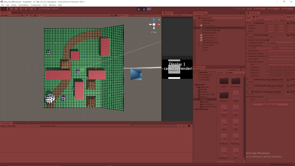
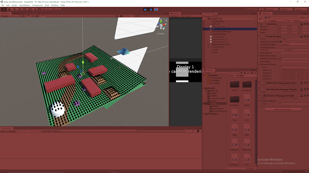
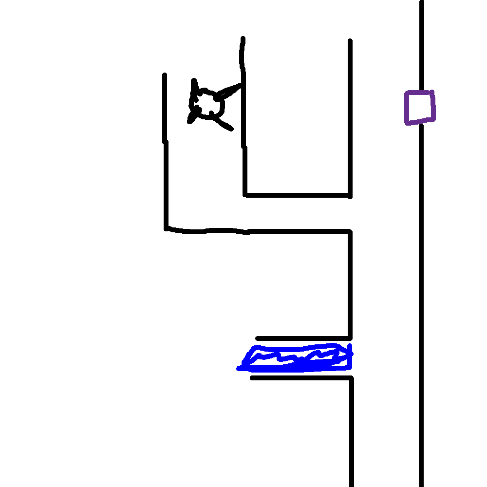
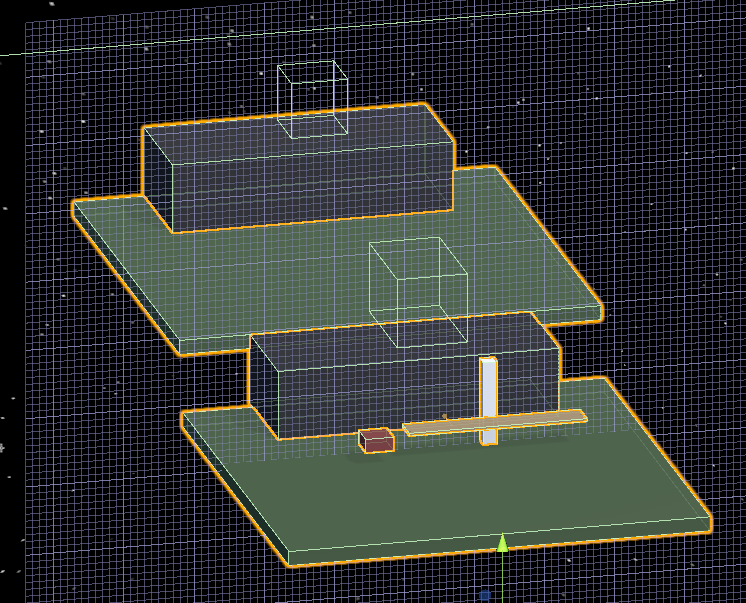
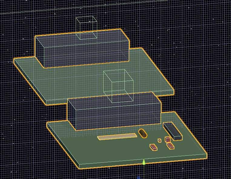
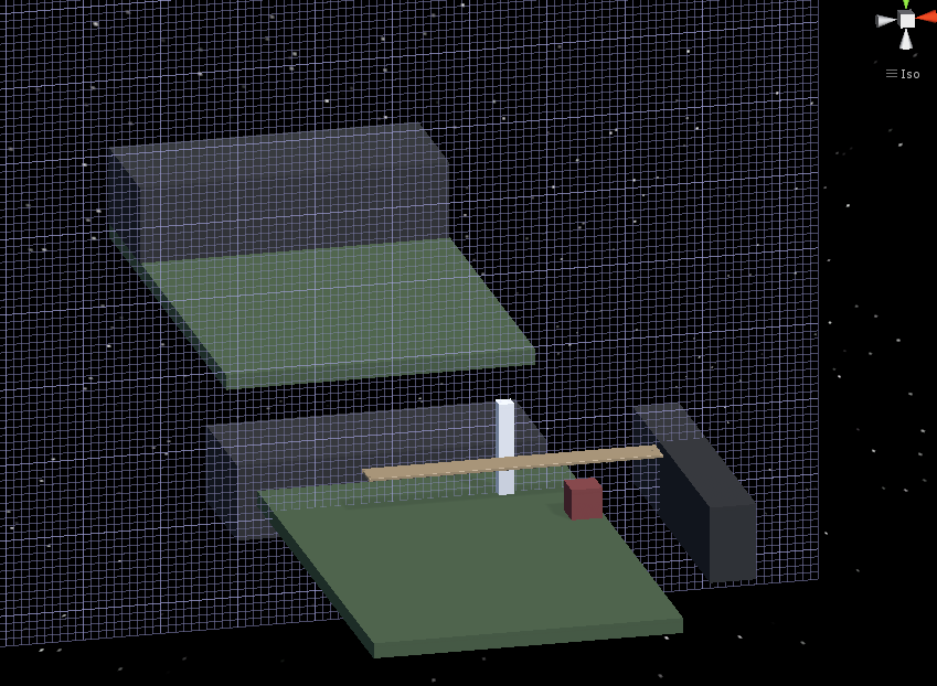
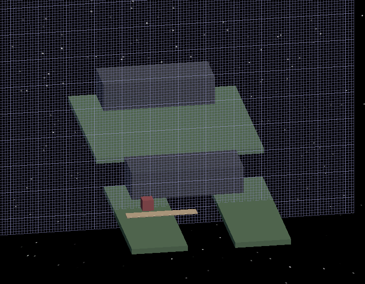
I have started to implement my approach outlined in my blog post from yesterday to create the foundation for this architectural pathing addition. I have started with just a single data point to work out the feature by adding a “window” value to both the agents and the nodes of the grid. The Agent window measures their affinity for window spaces (higher value means they are more likely to move near/towards windows) and the Node window values represents how much that space is influenced by windows (being closer to a window or near several windows will raise this value, and a higher value means it is more window influenced, and more appealing to high window affinity agents).

I modified the existing Influence class into an abstract base class that I will use as the basis for these architectural influence objects. This allows me to pass on traits consistent with all types of influence objects (such as dimensions for area of influence) as well as methods they will all need (such as one which determines how they apply influence to the area around them). Related to this, I was able to move the influence method out of the AGrid class, which also prepares the entire grid, so this was good for trimming that class down.

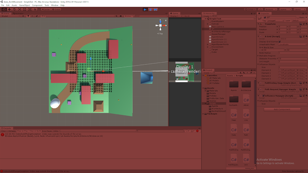
Moving the influence spreading methods to the Influence objects themselves was also crucial because it allows different objects to apply influence differently and more uniquely. Some objects may apply to simple rectangular shapes, where others may project out in a cone, or even use ray casts to determine their area of influence. To help these Influence objects influence the proper area, I pass them a reference to the grid as well as their starting position (in terms of nodes on the grid). This is helpful to start in the AGrid class, which currently holds a reference to all the Influence objects in the scene, as it uses their transform information to determine which node they are centered on (which is passed on to the Influence object itself as stated to know where it is located in the grid).

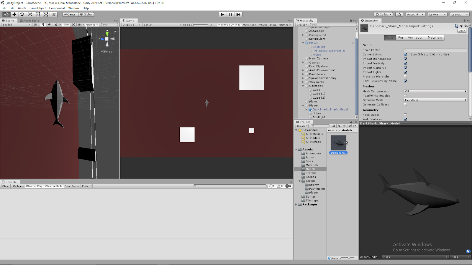
Finally, I had to make sure a reference to the individual agents was getting passed through the entire pathfinding process so it could use that information to provide the possibly unique path for the different types of agents. This just meant I needed to add references to the UnitSimple class to pass through as a parameter from UnitSimple itself, to the PathRequestManagerSimple, and eventually to the PathfindingHeapSimple, which finally uses that data to modify how it calculates cost for creating the paths.

Investigating How to Apply Architectural Influence as Cost

Figuring out how to apply this combination of architectural value within the nodes themselves and the architectural affinities of the agent in a mathematical sense that makes sense has proven difficult, and I am still investigating a clean way to implement this. Because of the nature of how the costs work with this pathfinding system, subtracting values from costs in a way that is not very controlled can be risky and prone to breaking, as negative values can provide some very strange results.

To help determine a system to implement this, I broke it down as simply as I could. The goal is to use the two values, agent affinity and node architectural value, together to produce a architectural cost to add on top of the normal distance cost of a node. Looking at this, I created a set of constraints to guide the process, and eventually a basic system to follow for now to give results at least in the proper realm of what we are looking for.

Architectural Cost Constraint Breakdown

Early on I thought it would be helpful to have a MAX affinity value possible and a MAX architectural value possible since I thought I would either need to subtract from these values (so bigger numbers led to lower additional cost) or divide with these numbers (to provide some proportionality value within the cost calculation). These arbitrary values and their concept were then used in coming up with some of the initial constraints I delivered. These constraints were (the results are the architectural cost, added to total node cost):

  • MAX Affinity with MAX Architectural Value = 0
  • MIN Affinity with MAX Architectural Value = MAX Architectural Cost
  • Average Affinity with ANY Architectural Value = DEFAULT
  • ANY Affinity with 0 Architectural Value = DEFAULT

The ideas behind these constraints were: having the highest affinity on the most architectural value possible on a node should produce the lowest architectural cost possible (0 in this case), the lowest affinity (or greatest aversion) with the highest architectural value on a node should produce the highest architectural cost possible, having an average affinity means the agent is neatural towards that architectural element so no value has any major influence on the cost, and finally if a node has 0 architectural value for a feature the agent takes on no cost regardless of their affinity towards it since it is not present in any way for that node.

Further Breakdown of Interaction Between Agent Affinity and Architectural Node Value

While a step in the right direction, I still was not sure exactly how I wanted to numerically determine the architectural cost. To further aid myself, I settled on a system that made a decent amount of sense with how I wanted these factors to interact. The tricky part is that it is the interaction between these two factors that influences the resulting cost on the node, it is not simply more of one or more of the other reduces cost on their own.

They concept I settled on was that the agent’s affinity value would be used to calculate a cost/architectural value factor (using basic factor labeling, multiplying this by architectural value would result in some cost value). I decided having a MAX affinity value possible made sense, and could help with this approach. Affinities below the average (value in the middle) of the MIN and MAX affinities would increase the cost of the node, where values above the average would reduce the cost of the node. The architectural value would then just determine how much this rate influenced the cost of the node. This correctly hit the points that agents with very low affinities should really want to avoid nodes with a lot of that architectural element, and those with very high affinities should really prefer nodes with that architectural element.

I feel like at this point I have most of the constraining factors and rules in place, I just need to bring them all together in a relatively clean calculation. My first attempt does not need to be the perfect solution, so I can modify it later if certain mathematical approaches work better for this situation, I just need to make sure it encompasses the general ideas and goals we need from the system for now.

Next Steps

I mostly just need to bring everything together to get a calculation that satisfies our basic rules and goals for now. As stated, I can modify it if better mathematical approaches are found, but we just need something to test for now. I am investigating basic math formulas to see which curves look like they would fit the preferred results, so I will at least record those for now to test in the future (just simple squared, cubed, root graphs). Finally, I just need to fully implement the system so I can test the bare basics to make sure the different agents actually travel differently with the window objects in the world and that they are not reducing the processing time to a crawl.

Updating A* for Multiple Agent Types of Pathfinding

March 20, 2020

Updating A*

Different Pathfinding Logic for Different Agent Types

A* Current System

The A* Pathfinding currently performs the same calculations for every agent in order to determine its path. Every unit then takes the same path assuming they have the same starting and target positions. We are looking to adjust this so there are various types of agents which with different affinities to certain objects in the environment. This then needs to be incorporated in the path determination so different types of agents will takes different paths, even when using the same starting position and same target position.

Differentiating Pathfinding for Different Types of Agents

We want to add more parameters to the grid nodes besides flat cost that influence the agents’ paths. These parameters also need to be able to influence different agents’ paths differently (i.e. the parameters may give a node a cost of 10 for one agent, but 20 for another).

Approach

The initial needs for this system are the addition of parameters to the nodes of the A* grid and parameters that correlate with these on the agents themselves. With this in place, we are just going to add a reference pass of the individual agents themselves to the eventual path calculation so it can also factor in these additional values.
The actual steps for this concept are laid out here:

– Individual agents need to have data within them that determines how they act
– Pass the UnitSimple instance itself through PathRequestManagerSimple.RequestPath along with the current information (its position, its target position, and the OnPathFound method)
– In PathRequestManagerSimple script, add UnitSimple variable to the PathRequest struct
– Now, RequestPath with added UnitSimple parameter can also pass its UnitSimple reference to its newly created PathRequest object
– Then, TryProcessNext method is run
– Here, the UnitSimple reference can be passed on to PathfindingHeapSimple through the pathfinding.StartFindPath() method call
– Add UnitSimple parameter to StartFindPath method in PathfindingHeapSimple class along with existing parameter (start position of path request, target position of path request)
– PathfindingHeapSimple can now use variables and factors of UnitSimple when determining and calculating the path for that specific agent
– Finally, returns its determined path as a set of Vector3 waypoints to the agent (effectively stays the same process)

Next Steps

This is just a conceptual plan, so I still need to implement it to see if it works and how it runs. I will also be looking to add some parameters to the nodes and agents, so I can start differentiating various types of agents to test the system.

HFFWS Thesis: Hand Built Lever Puzzles to Learn From

April 16, 2020

Hand Building Puzzles

Thesis Project

Intro

Following hand building the ramp puzzles to learn from for my thesis project, I have built lever puzzles to continue the process.

Current Hand Made Ramp Puzzles

As stated previously, this section was about creating the lever puzzles this time around. The main ideas behind them in order are: testing ramps, lift heavy object, build a lever system, launch a projectile, jam lever, and cantilever.

Puzzle 1: Testing

Just as a place holder, I kept a puzzle testing scenario in my Unity project scene just to test physics objects and keep references for ramp angles that work and platform sizes for different scenarios.

Puzzle 2: Lift Heavy Object

This scenario uses a premade seesaw in the scene to allow the player to access new locations. This is the base lever interaction as it gives a really simple environment for the player to focus on playing with a large lever object with their player character and get a base feel for how it operates when masses and forces are applied at different points along the lever. They then eventually use this knowledge to lift a heavy object somewhere with the seesaw they could not reach just by lifting it with the player.

Basic Seesaw Puzzle Scenario


Puzzle 3: Build a Lever System

The resulting puzzle is similar to Puzzle 2, but the player is just given the parts of a lever system to work out how to put them together to create an effective lever. They are given a long platform object to operate as the main body of the lever, as well as several larger massive objects to maneuver in a way to create a fulcrum, support the fulcrum, and even use a weight to hold parts of the system in place while they operate on it.

Building a lever system in HFF can be a bit finicky, so I will need to experiment with what types of masses and objects work best to provide a workable system for the player. This is a very interesting concept overall as it provides a much more insightful application of knowledge for placement of the fulcrum and how it effects the overall system.

Build a Lever Puzzle Scenario


Puzzle 4: Launch Projectile

This puzzle uses a very large difference in mass between two main objects to show transfer of energy in a dramatic fashion. A very small and light object is placed on one end of a lever system, then an extremely massive object is pushed from a great height onto the other end to launch the small object as a projectile to a new location.

Launch a Projectile Lever Puzzle Scenario


Puzzle 5: Jam Lever

These scenarios focus on giving the player an object which they can use to restrict the movement of the lever. Many uses of the scenario focus on adding masses on top of the lever, but this scenario focuses on the player placing masses in the direction of motion of a lever in order to stop it from moving and position it in places it could not otherwise allow them to reach. This can help the player use a lever to cross very long gaps with only minimal mass in objects, since the objects are not used as torque providers.

Jam Lever Puzzle Scenario


Puzzle 6: Cantilever

These scenarios also allow the player to cross significant gaps, by having the player restrict a lever or apply a counter torque to one end of a lever so that it does not move as they move across it (or move another mass across it) as it hangs over a gap. This can be done by hanging a very long platform object over a gap and either setting a very large mass on one end, or jamming the end of the lever under something very static (similar to the inverse of the jam lever scenario above).

Cantilever Lever Puzzle Scenario


Summary

The lever puzzles have already shown to be significantly more complex to setup than the ramp puzzles. The large focus on torque with lever scenarios makes them a lot more complex, as the dimensions of objects as well as their masses need to be coordinated properly to generate solvable scenarios. Messing either of these up will quickly lead to issues where the levers are uncontrollable.

Completed Prototype Model of a Shark for Dark Shark Project

April 14, 2020

Model Shark for Dark Shark

Modeling in Maya 2019

Modeling a Shark – Pt 4

Youtube – Tutorial #1

By: Dan Pejril


Summary

I followed parts 4 and 5 of this tutorial series on Youtube to guide my process for making my shark model for the Dark Shark project. Part 4 helped me with finding a way to mirror objects in Maya to create the pectoral fins for the model. The approach they used was to delete half the faces of the model to then duplicate the remaining half with “Duplicate Special” and scale -1.0 in the x. This way anything done on the one half of the model was duplicated on the other side.

Part 5 got more into creating the mirrored objects and merging it back together. After creating the pectoral fins, they then needed to combine the two halves back into a single mesh. This was done with “Combine”. This unites the individual meshes into one, this however does not really modify the verts and edges. To complete the combination, they used a “Merge” to join the verts and edges that are very close together. This properly completes combining the mesh.

Results

I was pretty happy with the results since I had not modeled in a while. I was just looking to make a simple, low poly, prototype model for now that I could just use as an effective place holder for now in the transition to make my game project in 3D. My Dark Shark project uses the orthographic view from the top, so the character silhouette from the top view is the most important so I focused on making that stand out and look nice. I am still working on how to cleanly represent the dorsal fin and tail fins in this view, but I made sure the pectoral fins were clearly visible to really drive home the imagery of a shark.

Shark Model in Maya

Shark Model in Unity and Game View

Modeling a Shark Player for Dark Shark Project

April 13, 2020

Model Shark for Dark Shark

Modeling in Maya 2019

Modeling a Shark – Pt 1

Youtube – Tutorial #1

By: Dan Pejril


Summary

I am looking to convert my original Dark Shark small game project from a 2D game to a 3D game as I progress with it, so I am using this as an opportunity to practice using Maya as a 3D modeling software and the pipeline of migrating models from there into Unity, since I haven’t done either in a while. My main focus is the gameplay and designing the underlying game systems, so I do not need an amazing model for now. This will just be practice so I’m making a simple, low-poly shark just to act as a place holder for now, and I can always upgrade it and make it nicer later if I want.

The video tutorial I have linked is a simple tutorial for modeling a simple shark, so I am using it as a rough reference as I brush up on the basics of using Maya as well as helping me design the shark a bit. As I mentioned, I’m just looking for a simple blocky low poly shark for now, so I am not dealing with some of the finer details from the tutorial, and ignoring details such as smoothing.

Some of the techniques it has helped me brush up on so far are: adding edge loops, selecting/moving/scaling verts/faces/edges, and extrusion. This is after going through the first three parts of this modeling tutorial series. I have done all this before, but it has been a long time now so it was helpful just to have a bit of guidance to remember which techniques to use when.

UnityLearn – AI For Beginners – Finite State Machines – Pt.02 – Finite State Machine Challenge

April 6, 2020

AI For Beginners

Finite State Machines

Finite State Machines


Beginner Programming: Unity Game Dev Courses

Unity Learn Course – AI For Beginners

Finite State Machine Challenge

This tutorial provided a challenge to complete and then provided a solution. The challenge was to create a state where the npc would retreat to an object tagged as “Safe” when the player approached the NPC closely from behind.

My Approach

Since they had a State enum named Sleep already that we had not worked with yet, I used that as the name of this new state (I started with Retreat, but then found the extra Sleep enum so I changed to that since I assumed it would be more consistent with the tutorial). Similar to the CanSeePlayer bool method added to the base State class for detecting when the player is in front of the NPC, I added an IsFlanked bool method here that worked similarly, but just detected if the player was very close behind instead of in front. I used this check in the Patrol and Idle state Update methods to determine if the agent should be sent into the new Sleep state.

In the Sleep state itself I used similar logic from the Pursue state for the constructor, so I set the speed to a higher value and isStopped to false so the NPC would start quickly moving to the safe location. In the Enter stage I found the GameObject with tag “Safe” (since this was set in the conditions for the challenge to begin with) and used SetDestination with that object’s transform.position.

The Update stage simply checked if the npc got close to the safe object with a continuous magnitude vector check, and once it got close enough, it would set the nextState to Idle before exiting (since Idle quickly goes back to Patrol in this tutorial anyway, this is the only option really needed).

Finally, the Exit stage just performs ResetTrigger for isRunning to reset the animator and moves on to the next State (which is only Idle as an option at this time).

Their Approach:

Most of what they did was very similar, although they did make a new State named RunAway instead of the extra Sleep State, so I could have stuck with Retreat and been fine.

Notable differences were that they checked if the player was behind them by changing the order of subtraction when performing the direction check (changed player – npc to npc – player) where I just had the angle check use the negative forward vector of the npc instead of the positive vector. These give effectively the same results, but I liked my approach better since it matched up with what was actually being checked better.

They also set the safe gameObject immediately in the constructor, where I was setting this in the Enter stage of the State. Again, this basically gives the same results in most cases, but I think their approach was better here just because the sooner you perform and set that FindGameObjectWithTag the better I think just to make sure it has access when it does need it.

Finally, for their distance check to see if they had arrived at the safe zone, they used a native NavMeshAgent value, remainingDistance. I used the standard distance check of subtracting the vectors and checking the magnitude, so these again both give similar results. Mine is more explicit in how it is checking, and the NavMeshAgent value is just cleaner, so these both had pros and cons.

Summary

This was a nice challenge just to work with a simple existing finite state machine. Similar to what they mentioned in the tutorial, I think setting the safe object in the static GameEnvironment script and just pulling from that (instead of using FindGameObjectWithTag every time the NPC enters the Sleep/RunAway State) would be much more efficient. Also just to help with checking states and debugging, I added a Debug.Log for the base State Enter stage method that just returned the name of the current State as soon as it was entered each time. This let me know which State was entered immediately when it was entered, so this also helped show me when the states were entered, so this was a very nice state machine check that only required a single line of code.

HFFWS Thesis: Hand Built Ramp Puzzles to Learn From

April 2, 2020

Hand Building Puzzles

Thesis Project

Intro

I have started crafting some small puzzle scenarios by hand to get a better idea of what types of concepts and parameters to take into consideration when creating a system to generate these types of scenarios. Researching them has only done so much, so I am helping to understand the relationships between objects within a scenario better by actively thinking through how to put them together.

Tracking Manual Puzzle Building

As I create each puzzle scenario, I have a list of data to keep track of that will hopefully help me better understand how to systematically put these scenarios together. These core ideas are: description, objects, position relations, parameter relations, skills, and concepts.

  • Description: General idea of what the puzzle scenario is and the main objective throughout
  • Objects: a list of all the objects used to make the puzzle scenario
  • Position Relations: information on how the different objects in the scenario must be placed relative to each other in order for the scenario to funciton properly (i.e. something must be placed higher than something else)
  • Parameter Relations: Similar to position relations, but with the parameters of each object; what data within each object must be within certain value ranges in order for the scenario to work (i.e. mass restrictions on certain objects)
  • Skills: what basic Human: Fall Flat gameplay skills are necessary from the player’s perspective to complete the scenario
  • Concepts: what knowledge the player must possess to understand how to complete this puzzle scenario

Current Hand Made Ramp Puzzles

I started with making ramp puzzles since they should be the simplest and help setup the general approach to this entire process. So far I have created 5 puzzle scenarios (the first of which is more of a ramp testing area). The main ideas behind them in order are: testing ramps, basic ramp, build a ramp, cross a gap with a ramp, and destroy a wall with a ramp.

Puzzle 1: Testing

This is not particularly a puzzle scenario. It is mostly just an area to test different sizes and scales of basic ramp objects to get an idea of what is manageable, scalable, and usable. This helps determine some of the dimensional restraints for the ramp objects in all cases to make sure the ramps generated are usable at all.

Testing Puzzle Area


Puzzle 2: Basic Ramp

This is more of the scenario extension of the testing area. It simply shows the most basic scenario where a ramp is provided, it just needs moved in place to allow the player to move to a higher elevation.

Basic Ramp Puzzle Scenario


Puzzle 3: Build a Ramp

This scenario provides the player with several physics objects which can be used together in such a way that they can build their own ramp to reach a higher elevation. At its core, this just requires some relatively long objects, a sturdy object to use as a central fulcrum to elevate the long object, and usually a weighted object to counter balance the torque generated by the player as they move up the long ramp object.

Build a Ramp Puzzle Scenario


Puzzle 4: Cross Gap with Ramp

This scenario type utilizes the fact that a ramp can also fulfill some properties of a bridge to span gaps, while still using the fact that the ramp helps move objects across elevations as well. Positioning ramps with this idea in mind is tricky since a lot of cases can lead to the ramp sinking into the gap if the player cannot get it cleanly across immediately.

Cross Gap with Ramp Puzzle Scenario


Puzzle 5: Destroy Wall with Ramp

Ramps help facilitate the movement of rolling objects in a way the player cannot accomplish by simply pushing them along the ground. Gravity helps move a rolling object down a ramp, accelerating it to allow it to reach speeds the player could not generally achieve on their own. This significant speed allows the rolling objects to apply a lot of force near the bottom of the ramp, which can greatly exceed that of the player in the right circumstances. This force can be used to destroy some of the destructible walls or environments in Human: Fall Flat to allow for progression.

Destructible Wall Ramp Puzzle Scenario


Summary

I will continue exploring these various puzzle scenarios since they both give me a better understanding of the relationships for proper puzzle generation as well as help give me ideas to expand the eventual puzzle generators capabilities. The basic testing area has helped give me some base parameters to work with, such as usable ramp slopes and general movable object masses, and the more advanced scenarios are helping uncover the multitude of relationships I need to keep together when building out these systems.