Modeling a Shark Player for Dark Shark Project

April 13, 2020

Model Shark for Dark Shark

Modeling in Maya 2019

Modeling a Shark – Pt 1

Youtube – Tutorial #1

By: Dan Pejril


Summary

I am looking to convert my original Dark Shark small game project from a 2D game to a 3D game as I progress with it, so I am using this as an opportunity to practice using Maya as a 3D modeling software and the pipeline of migrating models from there into Unity, since I haven’t done either in a while. My main focus is the gameplay and designing the underlying game systems, so I do not need an amazing model for now. This will just be practice so I’m making a simple, low-poly shark just to act as a place holder for now, and I can always upgrade it and make it nicer later if I want.

The video tutorial I have linked is a simple tutorial for modeling a simple shark, so I am using it as a rough reference as I brush up on the basics of using Maya as well as helping me design the shark a bit. As I mentioned, I’m just looking for a simple blocky low poly shark for now, so I am not dealing with some of the finer details from the tutorial, and ignoring details such as smoothing.

Some of the techniques it has helped me brush up on so far are: adding edge loops, selecting/moving/scaling verts/faces/edges, and extrusion. This is after going through the first three parts of this modeling tutorial series. I have done all this before, but it has been a long time now so it was helpful just to have a bit of guidance to remember which techniques to use when.

UnityLearn – AI For Beginners – Finite State Machines – Pt.02 – Finite State Machine Challenge

April 6, 2020

AI For Beginners

Finite State Machines

Finite State Machines


Beginner Programming: Unity Game Dev Courses

Unity Learn Course – AI For Beginners

Finite State Machine Challenge

This tutorial provided a challenge to complete and then provided a solution. The challenge was to create a state where the npc would retreat to an object tagged as “Safe” when the player approached the NPC closely from behind.

My Approach

Since they had a State enum named Sleep already that we had not worked with yet, I used that as the name of this new state (I started with Retreat, but then found the extra Sleep enum so I changed to that since I assumed it would be more consistent with the tutorial). Similar to the CanSeePlayer bool method added to the base State class for detecting when the player is in front of the NPC, I added an IsFlanked bool method here that worked similarly, but just detected if the player was very close behind instead of in front. I used this check in the Patrol and Idle state Update methods to determine if the agent should be sent into the new Sleep state.

In the Sleep state itself I used similar logic from the Pursue state for the constructor, so I set the speed to a higher value and isStopped to false so the NPC would start quickly moving to the safe location. In the Enter stage I found the GameObject with tag “Safe” (since this was set in the conditions for the challenge to begin with) and used SetDestination with that object’s transform.position.

The Update stage simply checked if the npc got close to the safe object with a continuous magnitude vector check, and once it got close enough, it would set the nextState to Idle before exiting (since Idle quickly goes back to Patrol in this tutorial anyway, this is the only option really needed).

Finally, the Exit stage just performs ResetTrigger for isRunning to reset the animator and moves on to the next State (which is only Idle as an option at this time).

Their Approach:

Most of what they did was very similar, although they did make a new State named RunAway instead of the extra Sleep State, so I could have stuck with Retreat and been fine.

Notable differences were that they checked if the player was behind them by changing the order of subtraction when performing the direction check (changed player – npc to npc – player) where I just had the angle check use the negative forward vector of the npc instead of the positive vector. These give effectively the same results, but I liked my approach better since it matched up with what was actually being checked better.

They also set the safe gameObject immediately in the constructor, where I was setting this in the Enter stage of the State. Again, this basically gives the same results in most cases, but I think their approach was better here just because the sooner you perform and set that FindGameObjectWithTag the better I think just to make sure it has access when it does need it.

Finally, for their distance check to see if they had arrived at the safe zone, they used a native NavMeshAgent value, remainingDistance. I used the standard distance check of subtracting the vectors and checking the magnitude, so these again both give similar results. Mine is more explicit in how it is checking, and the NavMeshAgent value is just cleaner, so these both had pros and cons.

Summary

This was a nice challenge just to work with a simple existing finite state machine. Similar to what they mentioned in the tutorial, I think setting the safe object in the static GameEnvironment script and just pulling from that (instead of using FindGameObjectWithTag every time the NPC enters the Sleep/RunAway State) would be much more efficient. Also just to help with checking states and debugging, I added a Debug.Log for the base State Enter stage method that just returned the name of the current State as soon as it was entered each time. This let me know which State was entered immediately when it was entered, so this also helped show me when the states were entered, so this was a very nice state machine check that only required a single line of code.

HFFWS Thesis: Hand Built Ramp Puzzles to Learn From

April 2, 2020

Hand Building Puzzles

Thesis Project

Intro

I have started crafting some small puzzle scenarios by hand to get a better idea of what types of concepts and parameters to take into consideration when creating a system to generate these types of scenarios. Researching them has only done so much, so I am helping to understand the relationships between objects within a scenario better by actively thinking through how to put them together.

Tracking Manual Puzzle Building

As I create each puzzle scenario, I have a list of data to keep track of that will hopefully help me better understand how to systematically put these scenarios together. These core ideas are: description, objects, position relations, parameter relations, skills, and concepts.

  • Description: General idea of what the puzzle scenario is and the main objective throughout
  • Objects: a list of all the objects used to make the puzzle scenario
  • Position Relations: information on how the different objects in the scenario must be placed relative to each other in order for the scenario to funciton properly (i.e. something must be placed higher than something else)
  • Parameter Relations: Similar to position relations, but with the parameters of each object; what data within each object must be within certain value ranges in order for the scenario to work (i.e. mass restrictions on certain objects)
  • Skills: what basic Human: Fall Flat gameplay skills are necessary from the player’s perspective to complete the scenario
  • Concepts: what knowledge the player must possess to understand how to complete this puzzle scenario

Current Hand Made Ramp Puzzles

I started with making ramp puzzles since they should be the simplest and help setup the general approach to this entire process. So far I have created 5 puzzle scenarios (the first of which is more of a ramp testing area). The main ideas behind them in order are: testing ramps, basic ramp, build a ramp, cross a gap with a ramp, and destroy a wall with a ramp.

Puzzle 1: Testing

This is not particularly a puzzle scenario. It is mostly just an area to test different sizes and scales of basic ramp objects to get an idea of what is manageable, scalable, and usable. This helps determine some of the dimensional restraints for the ramp objects in all cases to make sure the ramps generated are usable at all.

Testing Puzzle Area


Puzzle 2: Basic Ramp

This is more of the scenario extension of the testing area. It simply shows the most basic scenario where a ramp is provided, it just needs moved in place to allow the player to move to a higher elevation.

Basic Ramp Puzzle Scenario


Puzzle 3: Build a Ramp

This scenario provides the player with several physics objects which can be used together in such a way that they can build their own ramp to reach a higher elevation. At its core, this just requires some relatively long objects, a sturdy object to use as a central fulcrum to elevate the long object, and usually a weighted object to counter balance the torque generated by the player as they move up the long ramp object.

Build a Ramp Puzzle Scenario


Puzzle 4: Cross Gap with Ramp

This scenario type utilizes the fact that a ramp can also fulfill some properties of a bridge to span gaps, while still using the fact that the ramp helps move objects across elevations as well. Positioning ramps with this idea in mind is tricky since a lot of cases can lead to the ramp sinking into the gap if the player cannot get it cleanly across immediately.

Cross Gap with Ramp Puzzle Scenario


Puzzle 5: Destroy Wall with Ramp

Ramps help facilitate the movement of rolling objects in a way the player cannot accomplish by simply pushing them along the ground. Gravity helps move a rolling object down a ramp, accelerating it to allow it to reach speeds the player could not generally achieve on their own. This significant speed allows the rolling objects to apply a lot of force near the bottom of the ramp, which can greatly exceed that of the player in the right circumstances. This force can be used to destroy some of the destructible walls or environments in Human: Fall Flat to allow for progression.

Destructible Wall Ramp Puzzle Scenario


Summary

I will continue exploring these various puzzle scenarios since they both give me a better understanding of the relationships for proper puzzle generation as well as help give me ideas to expand the eventual puzzle generators capabilities. The basic testing area has helped give me some base parameters to work with, such as usable ramp slopes and general movable object masses, and the more advanced scenarios are helping uncover the multitude of relationships I need to keep together when building out these systems.

UnityLearn – AI For Beginners – Finite State Machines – Pt.01 – Finite State Machines

April 1, 2020

AI For Beginners

Finite State Machines

Finite State Machines


Beginner Programming: Unity Game Dev Courses

Unity Learn Course – AI For Beginners

Finite State Machines

Finite State Machine (FSM): conceptual machine that can be in exactly one of any number of states at any given time.
Represented by a graph where nodes are the states, and the paths between them are the transitions from one state to another. An NPC will stay in one state until a condition is met which changes it to another state.

Each state has 3 core methods: Enter, Update, Exit

  • Enter: runs as soon as the state is transitioned to
  • Update: is the continuous logic run while in this state
  • Exit: run at the moment before the NPC moves on to the next state

State Machine Template Code (Can use core of this for each individual state):

public class State
{
public enum STATE
{
IDLE, PATROL, PURSUE, ATTACK, SLEEP
};

public enum EVENT
{
ENTER, UPDATE, EXIT
};

public STATE name;
protected EVENT stage;

public STATE()
{ stage = EVENT.ENTER; }

public virtual void Enter() { stage = EVENT.UPDATE; }
public virtual void Update() { stage = EVENT.UPDATE; }
public virtual void Exit() { stage = EVENT.EXIT; }

public State Process()
{
if (stage == EVENT.ENTER) Enter();
if (stage == EVENT.UPDATE) Update();
if (stage == EVENT.EXIT)
{
Exit();
return nextState;
}
return this;
}
}

Creating and Using A State Class

State class template (similar but slightly different from last tutorial, with some comments):

public class State
{
public enum STATE
{
IDLE, PATROL, PURSUE, ATTACK, SLEEP
};

public enum EVENT
{
ENTER, UPDATE, EXIT
};

// Core state identifiers
public STATE name;
protected EVENT stage;

// Data to set for each NPC
protected GameObject npc;
protected Animator anim;
protected Transform player;
protected State nextState;
protected NavMeshAgent agent;

// Parameters for NPC utilizing states
float visionDistance = 10.0f;
float visionAngle = 30.0f;
float shootDistance = 7.0f;

public State(GameObject _npc, NavMeshAgent _agent, Animator _anim, Transform _player)
{
npc = _npc;
agent = _agent;
anim = _anim;
stage = EVENT.ENTER;
player = _player;
}

public virtual void Enter() { stage = EVENT.UPDATE; }
public virtual void Update() { stage = EVENT.UPDATE; }
public virtual void Exit() { stage = EVENT.EXIT; }

public State Process()
{
if (stage == EVENT.ENTER)
Enter();
if (stage == EVENT.UPDATE)
Update();
if(stage == EVENT.EXIT)
{
Exit();
return nextState;
}
return this;
}
}

Notice that the public virtual methods for the various stages of a state look a bit awkward. Both Enter and Update set the stage to EVENT.UPDATE because you want them to be setting stage equal to the next process called, and both of them would look to move that to Update. After entering, you move to Update, and each Update wants to move to Update again until it is told to do something else to Exit.

They also started to make actual State scripts, which create new classes that inherit from this base State class. The first example was an Idle state with little going on to get a base understanding. Each of the stage methods (Enter, Update, Exit) used the base versions of the methods from the base class as well as their own unique logic particular to that state. Adding the base methods within just ensured the next stage is set properly and uniformly.

Patrolling the Perimeter

This tutorial adds the next State for the State Machine, Patrol. This gets the NPC moving around the waypoints designated in the scene using a NavMesh.

They then create the AI class, which is the foundational logic for the NPC that will actually be utilizing the states. This is a fairly simple script in that the Update simply runs the line:

currentState = currentState.Process();

This handles properly setting the next State with each Update, as well as deciding which state to use and which stage of that state to run.

It turns out running the base Update method at the end of all the individual State classes’ Update methods was overwriting their ability to set the stage to Exit, so they could never leave the Update stage. They fixed this by simply removing those base method calls.

Summary

Using Finite State Machines is a clean and organized way to give NPCs various types of behaviors. It keeps the code clean by organizing each state of behaviors into its own class and using a central manager AI for each NPC to move between the states. This also helps ensure an NPC is only in a single state at any given time, to reduce errors and debugging.

This setup is similar to other Finite State Machine implementations I have run into in Unity. The Enter, Update, and Exit methods are core in any basic implementation.

UnityLearn – AI For Beginners – Navigation Meshes – Pt.02 – Navigation Meshes

March 30, 2020

AI For Beginners

Navigation Meshes

Navigation Meshes


Beginner Programming: Unity Game Dev Courses

Unity Learn Course – AI For Beginners

Navigation Mesh Introduction

Nav Mesh: Unity function for making a navigable area for agents to traverse over.

There are 4 main tabs in the Navigation window:

  • Agents
  • Area
  • Bake
  • Object

Agents

Core Parameters: Radius, Height, Step Height, Max Slope

These dimensions determine where the agent can fit when navigating around obstacles, as well as how it can traverse elevation differences. Radius and height help limit where a character can go (cannot go between very small gaps or under objects very close to the ground) where step height is the elevation difference it can traverse in a single jump and max slope is how inclined the surface can be for the agent to travel on. The name allows you to save several types of agents, with various values for these 4 core parameters.

Area

How you define different costs for different types of areas (used in A* pathing).

Bake

Creates the Nav Mesh over your given series of meshes using their polygons. It does this using a template agent called the baked agent size. By default there is only a single mesh created for the default agent type, but there are additional tools that can allow you to create multiple meshes to help handle various sized/types of agents. The Generated Off Mesh Links parameters determine how far off the mesh an agent should be able to jump or drop to get to another mesh location.

Advanced Options (Under Bake):
  • Manual Voxel Size: lets you determine the voxel size used to generate the Nav Mesh; larger voxels are less detailed and follow the mesh less accurately; default is 3.00 voxels per agent radius; generally aiming for a value between 2 and 4
  • Min Region Area: Helps remove areas that are deemed navigable, but are too small to really be of use or will cause issues by existing
  • Height Mesh: bool to determine if Nav Mesh should average elevations to turn steps into slopes or not

Object

Where you can align specific area types to different parts of the mesh, which parts of your mesh you want to generate nav meshes for, and helps create mesh links, which help travel from one nav mesh to another by jumping or falling.

From Waypoints to NavMesh

Introduction of Unity NavMesh, where they introduce the concept of baking the Nav Mesh with use of static game objects and adding the NavMeshAgent component to the AI agents you want to follow the Nav Mesh.

NavMeshAgents

They setup a new scene and project with a Nav Mesh. Nav Mesh specifically looks for “Navigation Static” game objects to build around when baking. They showed that selecting a gameObject before going into play mode with the Nav Mesh active helped visualize how the Nav Mesh was determining their paths.

Areas and Costs

The Areas tab in the Navigation Window lets you set different parts of the mesh as different types of areas. When selecting the polygons or meshes to use for these different areas, select the desired polygons and go to the Object tab. Here you can select which Area to apply to those specific polygons. These areas can then be used to tell agents where they can and cannot go. This is done by going to the NavMeshAgent component of the agent and changing the Area Mask of the Path Finding for that agent. By turning an Area type on or off, you designate which meshes it can travel on at all.

In the Areas tab, you can assign different Cost values to these different areas. This can make them more or less appealing for the agents to traverse across (higher values for cost mean the agents are less likely to use that path).

Following a Player on a NavMesh and Setting Up Off-Mesh Links

This tutorial setup another scene in another project, this time with the basis of following the player around. This was as simple as using the SetDestination method within the NavMeshAgent component to the player’s position in Update.

Off Mesh Links

Off Mesh Links: used if you have gaps in your NavMesh that you want an agent to cross

To create the Mesh Links, select the polygons of interest that you want to link over a gap and go to the Object tab. Here you can select “Generate Mesh Links”. Then go to the Bake tab, set the “Drop Height” and/or “Jump Distance” under the “Generated Off Mesh Links” section, and bake the mesh again to incorporate these links. They will be visually shown as circles between the meshes. Jump Distance is good for crossing horizontal disconnects, where Drop Height is good for crossing significant vertical disconnects. Setting drop links is similar, in that you select the two main groups of meshes in question and generate the mesh links.

Summary

After doing a lot of work with A*, building a path finding system with it from scratch, a lot of the tuning factors and parameters for Nav Mesh made a lot of sense with how A* works. This was good to know there was so much overlap, so I can learn a lot from what they use to work with Nav Mesh to give my A* system effective modifiable parameters to tweak it for designing needs.

Nav Mesh does seem powerful and very easy to get running, but I would have to work with it more to see just how controllable it is. I still like having my own A* system that I know the insides well to tweak exactly how I want it, but the Nav Mesh does offer a lot of similar features I am looking to add so I may need to explore it more to see how easy it is to work with.

A* Architecture Project – Spawning Agents and Area of Influence Objects

March 25, 2020

Updating A*

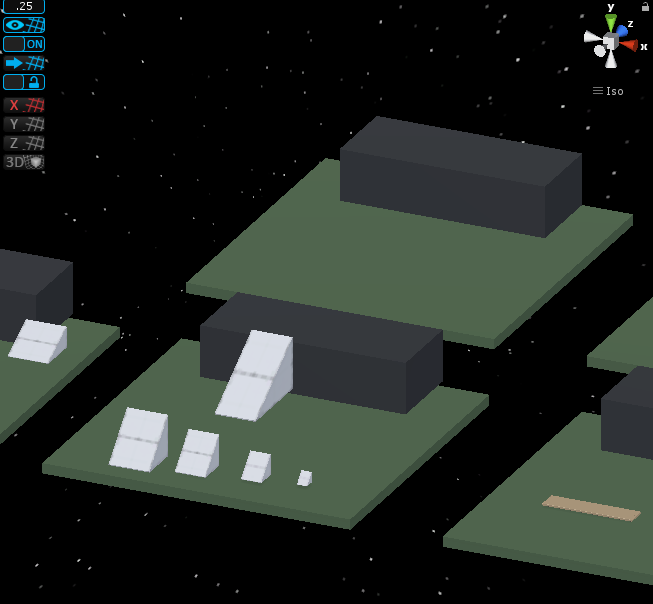
Spawn and Area of Influence Objects

Spawning Agents

Goal: Ability to spawn agents in that would be able to use the A* grid for pathing. Should have options to spawn in different locations and all use grid properly.

This was rather straight forward to implement, but I did run into a completely unrelated issue. I created an AgentSpawnManager class which simply holds a prefab reference for the agents to spawn, a transform for the target to pass on to the agents, and an array of possibl spawn points (for incorporating the option of several spawn locations). This class creates new gameObjects based on the prefab reference, and then sets their target to that determined by the spawner. This was something worth tracking since sometimes there can be issues with Awake and Start methods when setting values after instantiation.

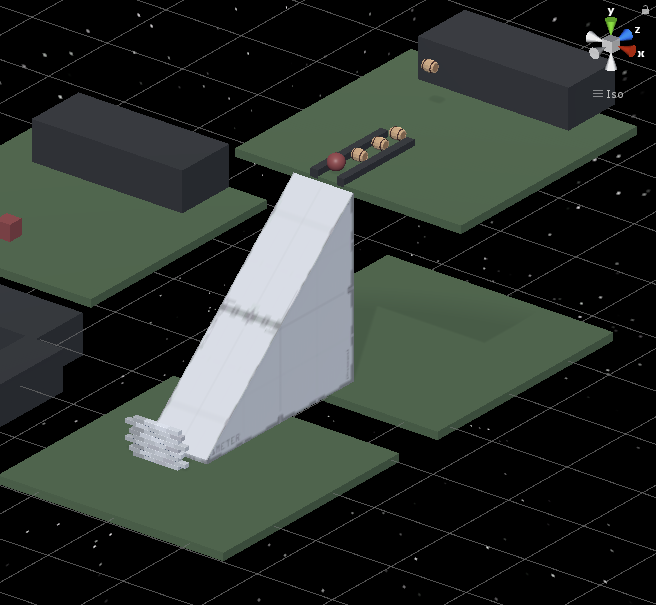
This was all simple enough, but the agents were spawning without moving at all. It turns out the issue was that the spawn location was above a surface that was above an obstacle (the obstacle was below the terrain, but entirely obstructed). This was an issue with how my ray detection and node grid was setup.

Editing the Grid Creation Raycast

The node and grid creation for the A* system uses a raycast to detect obstacles, as well as types of terrain to inform the nodes of their costs or if they are usable at all. Since it is very common to use large scale planes or surfaces as general terrain, and place obstacles on this, uses a full ray check would almost always pick up walkable terrain, even if it hit an obstacle as well.

To get around this, I simply had it check for obstacles first, and if it detected one, mark this node unwalkable and move on. This created an issue however in the reverse case, if an obstacle went a bit past the terrain into other nodes below the surface, they would be picked up as false obstacles, or in this case, it was picking up obstacles that were entirely located below the surface.

I was using a distance raycast in Unity, which just checks for everything over a set distance. I looked into switching this to a system that just detects the first collider the ray hits and simply use that information. I found that using the hit information of the raycast does this.

Unfortunately I am using a layer setup for walkable and unwalkable (obstacle) terrain, so I needed to incorporate that into my hit check. Checking layers is just weird and unreadable in Unity scripting, since I am currently just use the hardcoded integer value for the current layer number that is unwalkable when doing my check for obstacles. This does at least suffice to let the system work properly for now.

Influence Area with Objects

I wanted to be able to create objects which could influence the overall cost of nodes around them in an area significantly larger than the objects themselves. The idea is that a small but visible or detectable objects could influence the appeal of nodes around them to draw or push agents away from them.

For a base test, I created a simple class called Influence to place on these objects. The first value they needed was an influence int to determine how much to alter the cost of the nodes they reached with their influence. Then, to determine the influence range, I gave them an int each for the x and z direction to create dimensions for a rectangle of influence in units of nodes. I also added some get only variables to help calculate values from x and z to help center these influence areas in the future.

I then added an Influence array to the AGrid class which contains all the logic on initializing the grid of nodes and setting their values at start up. After setting up the grid, it goes through this array of Influence objects and uses their center transform positions to determine what node they are centered on, then finds all the nodes around it according to the x and z dimensions given to that influence object, and modifies their cost values with the influence value of the Influence object. Everything worked pretty nicely for this.

As a final touch just to help with visualization, I added a DrawGizmos method that draws yellow wire cubes around the influence objects to match their area of influence. Since the dimensions are mainly in node units, but the draw wire cube wants true Unity units, I simply multiplied the x and z node dimensions for the influence by the nodeDiamater (which is the real world size of each node) to convert it to units that made sense.

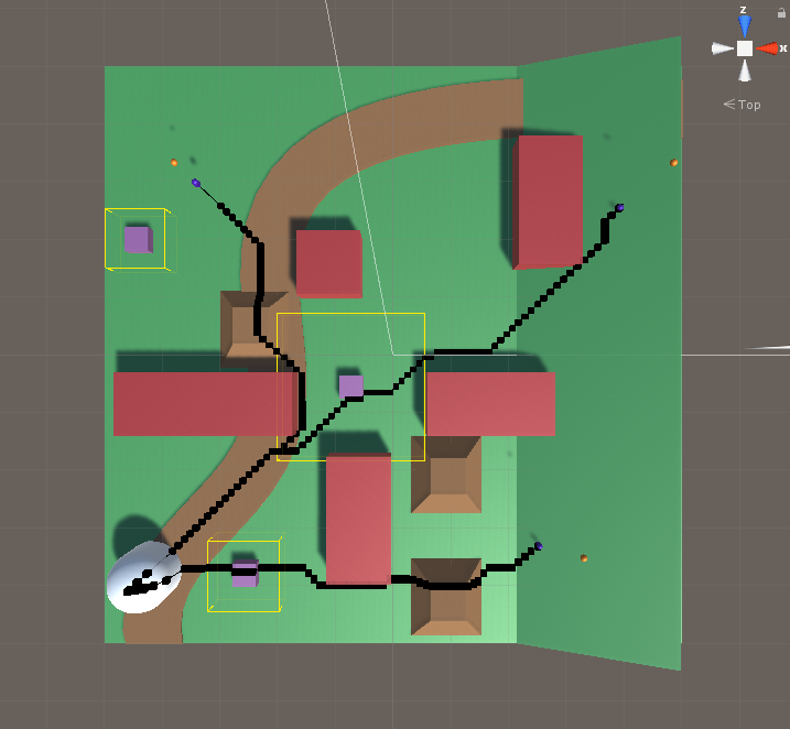
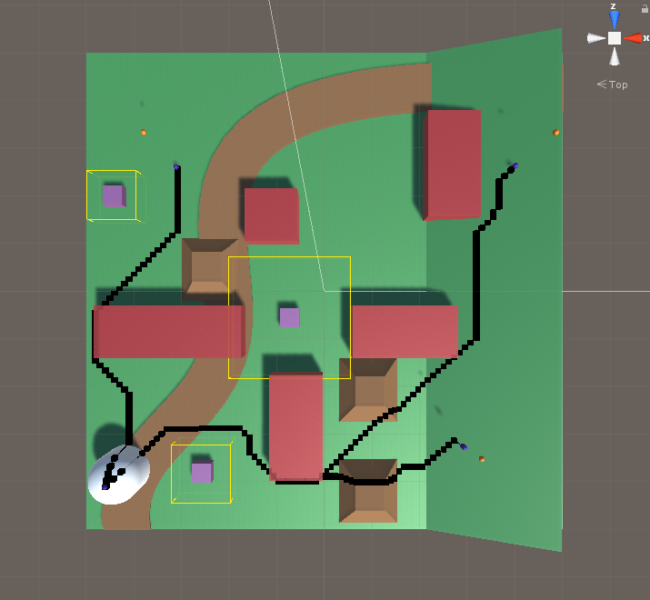
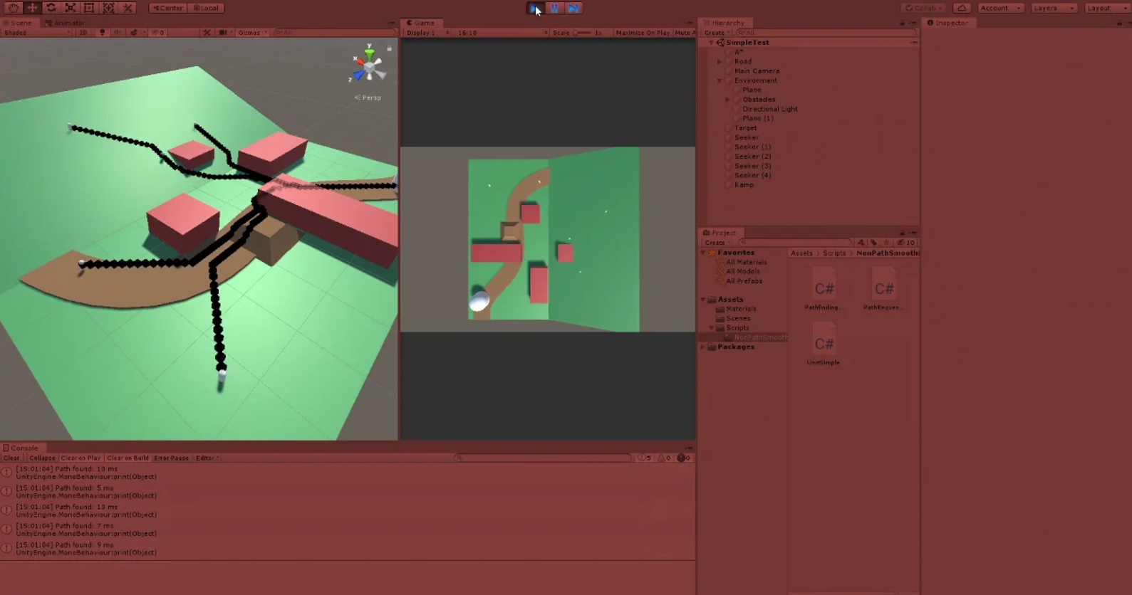
I have two sample images to show the influence objects in effect below. The small purple squares are the influence objects, and the yellow wire frame cubes around them show their estimated area of influence. The first image shows the paths of the agents when the influence of all squares is set to 0 (no influence), and the second shows the paths when the influence is set to 200 (makes nodes around them much more costly and less appealing to travel over).

Paths with Influence Set to 0


Paths with Influence Set to 200

Summary

The raycast and layer system for detecting the terrain and initializing the grid could use some work to perform more cleanly and safely, especially for future updates. The spawning seems to have no issues at all, so that should be good to work with and edit moving forward. The basic implementation of the influence objects has been promising so far, I will look into using that as a higher level parent class or an interface moving forward as this will be a large part of the project and their may be many objects that use this same core logic by want special twists on it (such as different area of influence shapes, or various calculations for how influence should be applied).

UnityLearn – AI For Beginners – Waypoints and Graphs – Pt.01 – Graph Theory

March 24, 2020

AI For Beginners

Graph Theory

Graph Theory


Beginner Programming: Unity Game Dev Courses

Unity Learn Course – AI For Beginners

Graph Theory

Intro

The AI for Beginners course starts very basic so I have not covered a lot up until now. It handles the basics of moving an object with simple scripting, as well as guiding and aiming that movement a bit. This section starts to get into some more interesting theory and background for AI.

Graphs are simply collections of nodes and edges. Nodes are locations or points of data, and edges are the paths connecting them (which also contain significant data themselves). There are two directional types for edges within these graphs: directed and undirected. Directed paths only allow for movement between two nodes in a single direction, while undirected paths allow for movement either direction between nodes.

Graphs are used in any case to move between states. These states can be real states or conceptual states, so the nodes and edges between them can possibly be much more theoretical then actual objects or locations.

Utility Value: This is the value for an edge. Some examples shown were time, distance, effort, and cost. These are values that help an NPC make a decision to move from one node to the next over said edge.

Basic High Level Algorithms for Searching Nodes

Breadth-First Search

Marks original node as 1, then all adjacent nodes to that as 2, then all adjacent nodes to all of those as 3, etc. until it reaches the destination node. It then counts backwards to determine the path. Examines all possible nodes in graph to find the best path. This makes it effective but expensive and time consuming.

Depth-First Search

Starts at NPC position, then finds one adjacent node and numbers it, then it finds another single adjacent node and numbers it. This continues until it finds a dead end, in which case it returns to the last node where there was another direction to try and heads off in a different direction with the same method.

More Advanced General High Level Algorithm

A* Algorithm

All the nodes are numbered. It creates an open list and closed list, which keep track of nodes visited. There are three main cost values associated with the edges in this case: Heuristic cost (H cost), Movement cost (G cost), and the F cost.
Heuristic Cost (H Cost): estimated cost of getting to the destination from that specific node (this value is generally distance related)
Movement Cost (G cost): utility cost of moving from one node to another node
F Cost: sum of the H cost and G cost which determines the total value of that node
Each node stores these cost values as well as its parent, which is the closest node that continues the proper path. Once the final node is reached, the nodes follow this chain of parent nodes to determine which nodes make up the path to travel.

Summary

This was a very simplified approach to graph theory that was at the very least helpful as a small refresher on how A* worked. I also learned that Unity’s NavMesh uses the A* algorithm at its foundation. This does give me a good starting point with some subjects and terminology to investigate to understand some theory behind AI however, with graph theory, the nodes and edges, and the basic search methods.

Updating A* to Move Units in 3D for Elevations (Cont.)

March 12, 2020

Updating A*

Adding 3D Movement (Elevations)

A* Current System and Notes

Now the A* system can deal with moving units along the y-axis according to the terrain, but it is still off with the advanced path smoothing functionality since this only cares about points where the unit is turning according to the xz-plane. To keep the system more simplified for now, I am looking to roll back some of the more advanced functionality from the Sebastian Lague tutorial I followed to incorporate the y-axis movement into a more simplified pathing system.

I want to ignore the SimplifyPath method for now (which narrows down the full list of nodes for a path down to only those which turn the agent, and only uses these as waypoints), which also causes problems if I have path smoothing as well. This is another reason to remove path smoothing temporarily.

A* Update

I wanted to keep the advanced path smoothing options available in the project, while looking to use the simplified version for now (with updates to continue having the y-axis movement). To do this, I identified which scripts dealt with path smoothing specifically which led me to the chain of these scripts:

  • PathFindingHeap
  • Unit
  • PathRequestManager

Since those were the scripts that dealt with applying path smoothing, I looked for versions of the project I saved as stepping stones of the tutorial that were before path smoothing (around episode 8 of the tutorials). From these projects, I grabbed their respective versions of these scripts to copy into this working project. To keep them as unique but separate options, I appended “Simple” to these versions of the scripts.

With these scripts, I could build out a scene (named SimpleTest) for the purposes of testing the y-axis movement with this simpler movement logic. While it is less aesthetically pleasing, it is in a way more accurate and representative of the core information the system is working with, so I wanted to get back to this state to have a better idea of what I was working with. This new scene has PathFindingHeapSimple and PathRequestManagerSimple on its A* gameobject, and each of the Seekers use the UnitSimple script instead.

With all of these in place to effectively remove path smoothing for now, I could effectively remove the SimplifyPath method from PathFindingHeap (and PathFindingHeapSimple as well for this case). This ensures the agents will travel to each individual position designated by every node along its path. This helps me see exactly every point of data that the agents are working with when moving. This is helpful to make sure the agents are properly receiving the right elevation data throughout the entirety of their paths.

With all of this done, I got the desired results I expected. The units immediately fly down into their starting position and move along the terrain properly, regardless of elevation. They effectively move up and down inclined surfaces, and can properly navigate up and down bumps and ramps in the terrain. They also show every single node point as a gizmo they are using as a path for movement, which clearly shows their paths following the terrain. I have included a video link for a quick demonstration of the agents in motion.

Vimeo – A* Movement in 3D Edit

AI Agents Moving in 3D with Path Highlighted

Next Steps

This simplified system appears to work exactly how I need it to, and I think this may be the preferred approach moving forward for now since it will be used to represent and show theoretical data. This may make it more practical to show the exact pathing information given as opposed to the skewed pathing created by the path smoothing operations.

The next step will be looking into creating objects which can influence the cost of a number nodes around them (as opposed to just those they are directly on, which is somewhat covered in the behavior of obstacles). This way different objects can influence the likelihood of an agent moving towards/around them.

I am looking at starting with a simple area of effect approach where the grid detects the object on a certain node and then alters the cost of all the nodes around it to some degree (the simpler approach, and mimics the blur effect already present from the tutorial followed). This blur effect makes it so the cost additions of the grass and road are blurred some around where they meet. The future advancement of this topic would be to allow objects to influence the cost of nodes based on line of sight, which is a much more variable amount of nodes to influence, making it a bit more difficult to implement.

HFFWS Thesis: Clearly Determining Space for Scenarios and Creating Barriers Between Them

March 11, 2020

Spacing Scenarios and Dividing with Obstacles

Thesis Project

Space Buffering

In the process of creating a simplified version of this generation system, I narrowed down the variability for now with a core focus on better defining the space a scenario has to work with. To keep it easier to work with, it is focused on a single axis for the most part, the x-axis, in spacing. This ties in to making the general space easier to define as well.

The overall spacing is mostly determined by spacing on the x-axis. The entire sequence of scenarios is constrained to a single overall platform with a fixed width, so every scenario is working with that same fixed width as well. The height does not particularly need to be constrained at this time, so determining a general x and z dimension for the space with an arbitrarily given y dimension works to define our space well for now.

Finally, to help visualize this space in the editor, I looked to DrawGizmos methods within Unity. I am currently creating a yellow wireframe cube centered at each of these central scenario locations with dimensions based on the scenario spacing (x-axis), the scenario width (z-axis), and an arbitrarily large height (y-dimension), each of which is determined within the DemoManager.

Creating Obstacles to Sequence the Scenarios

We wanted to start looking into having the chain of scenarios play into each other, so the first concept to look into for that was creating significant obstacles at the “end” of each scenario that needed to be overcome to reach the next one. The idea for the simplest approach for this was to create a significantly tall wall that covered the entire width of the play area and was placed at the end of the scenario space (the end on the x-axis). Again, to simplify the approach, this was investigated solely with ramp scenarios for now.

Creating this wall originates with using the existing CreateObstacleTerrain class I created, which basically makes various rectangular-shaped obstacles. The scenarioWidth information is passed into this creation to ensure that the wall covers the full width of the play area. The scenario spacing information passed from the DemoManager helps with the placement of this wall at the end of the scenario.

The order of operations follows that the ramp is generated, and then the obstacle. With this, the ramp height is recorded and passed on to the wall to determine its height range. This ensures the wall is tall enough to provide a challenge, but not so tall that it can not be overcome.

Finally, to help position this obstacle even more accurately, it is actually repositioned after its parameters are determined. The systems chooses the wall obstacle’s dimensions from its available options, and then feeds this data into a method to finally place the wall. This helps adjust the position of the wall for its thickness especially when making sure it fits in the end of the scenario area without going into the next area.

Updating A* to Move Units in 3D for Elevations

March 11, 2020

Updating A*

Adding 3D Movement (Elevations)

A* Current System

The current A* system I am using solely works on a 2D plane (on the x-axis and z-axis). It creates a grid on this 2D plane and then allows agents to move specifically along this 2D plane, with no regard for heights. It is currently casting rays from above these grid nodes to detect the layer of the terrain the node is on. Each node also casts a small sphere the same size as it to detect collision for obstacles to determine if a node is traversable or not.

A* Update

Since the system already uses raycasts to detect the terrain type, I edited this to detect the height information from the terrain as well. Using RaycastHit.point, the raycast can return information on the exact point it hits, so I can pass the y-axis information from here to the node. I just do this along with the terrain detection, and pass this to the world position data of the node.

Since this update is specifically targeted at working with various elevations, I do not like using the collision spheres on the nodes to detect obstacles. Since I already have raycast incorporated, I thought it made sense to have it detect obstacles as well. Because there are layers involved for obstacles and terrain, I have the raycast check first if it can detect an obstacle (unwalkable terrain), and then if it does not find one, then check for walkable terrain and what type it is.

Finally, just to clean up, I added an extra variable to account for the unit heights when assigning elevation positions. This can be changed in the editor, but it adds a bit of elevation to the exact value from the terrain so the unit’s positioning as it moves along is a bit above the ground (so it is not in or below the ground).

Next Steps

These changes worked pretty well to get close to the desired effects. The units will move along altered elevation terrains to some degree. The current testing was done with a further simplified waypoint system after grabbing all of the nodes, so only the position data of points where the unit needs to turn is really taken into account for movement. This results in weird issues since the unit will not move up and down to account for elevation if it is moving in a straight line according to the xz-plane. It only accounts for elevation if the specific waypoints end up on varied elevation points (this is why it looks pretty proper on just a slanted plane).

I will look into reverting the simplified system to see if the standard system going to every single node works first. After I get that working again in all 3 dimensions, I will look to adjust back to the simplified waypoints system.