July 1, 2021
Modding with Harmony
Monster Train
Title:
Getting Started with Trainworks Modding Tools
By:
KittenAqua
Description:
More detailed and in-depth documentation on properly setting up a C# project for modding Monster Train as well as examples for modding various content.
Title:
Harmony Patching Article
By:
Harmony
Description:
General documentation on Harmony.
Overview
As of the writing of this blog, the state of the Trainworks modding API with Monster Train after its DLC release is a bit rough. Creating custom cards was a core feature of Trainworks, but the DLC update has broken a lot of the original system. I have been investigating these issues to see if I can identify the problem(s) and potentially fix them. This has led me to learning a lot about using Harmony, a tool for modding Unity games, especially in a way to create logs to help me track bugs and problems when integrated with BepInEx.
Harmony Basics with Trainworks
The ‘Getting Started with Trainworks Modding Tools’ link above was very helpful in covering the basics of using Harmony with Monster Train. The most common methods used with these patches are ‘Postfix’ and ‘Prefix’.
Each patch is its own class, which contains methods performing the patching. It must also use attributes supplied by the Harmony API to indicate that it is a Harmony patch to be picked up when running the mod. This attributes for these cases generally contain information such as: the method name, the parameters of the method (if an overloaded method), and the class name containing said method.
Prefix and Postfix Arguments
The list of arguments covered by the ‘Getting Started…’ link above is:
- Any arguments the original method took, with the same type and name
- The instance of the class the method has been called on: ClassName __instance (two underscores)
- Any fields of the instance, whether public or private. They should have the same name and type as the original, but with three underscores before: FieldType ___fieldName
- The return value of the method: __result (two underscores)
- A couple other things that aren’t used as often. Reference the official Harmony documentation for details.
The ‘ref’ keyword is used with the Postfix and Prefix methods often. This is because it is common that you will want to take in a variable from the existing methods and actively change the value of said argument.
Postfix
Postfix patches are used to perform actions after a method in the established project (Monster Train in this case) is called. This means it also has access to the result of said method to read from it or even alter it.
Prefix
Opposite of the Postfix, Prefix methods are those which are executed before the original method. As such, they are uniquely situated to prevent the original method from even executing if wanted (although this is something that is advised to do with care as it can easily break systems relying on it running).
From the official Harmony documentation, these are commonly used to:
- access and edit the arguments of the original method
- set the result of the original method
- skip the original method and prefixes that alter its input/result
- set custom state that can be recalled in the postfix
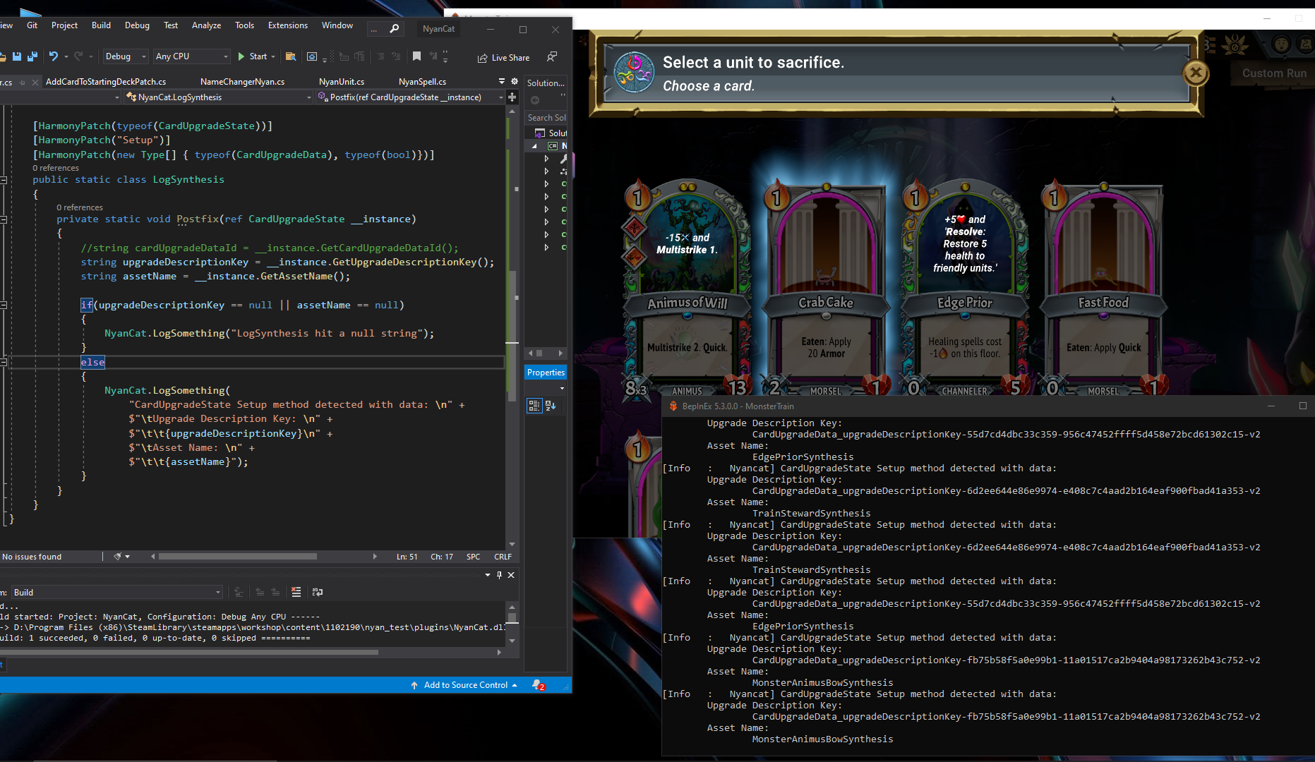
Example Logging Monster Train CardUpgradeData Setup Method
While investigating an issue with unit synthesis in the game, I encountered an error that led me to explore the Setup method in the CardUpgradeData class of Monster Train, as this appears to be a core part of the synthesis process. I decided to setup a Postfix method to return some information from this method when it was run (as well as to just help determine when this method was being run).
In this investigation I found that selecting existing units (which clearly have all the assets necessary) in the unit synthesis temple would call this method, along with a specialized unit synthesis upgrade. However, selecting a custom unit did not call this method at all. While this normally would make sense obviously since they do not have a unit synthesis upgrade made for them, the Trainworks tool is supposed to make a replacement synthesis upgrade in this case, which I thought may be picked up by this system.
Class for Logging
[HarmonyPatch(typeof(CardUpgradeState))]
    [HarmonyPatch("Setup")]
    [HarmonyPatch(new Type[] { typeof(CardUpgradeData), typeof(bool)})]
    public static class LogSynthesis
    {
        private static void Postfix(ref CardUpgradeState __instance)
        {
            //string cardUpgradeDataId = __instance.GetCardUpgradeDataId();
            string upgradeDescriptionKey = __instance.GetUpgradeDescriptionKey();
            string assetName = __instance.GetAssetName();

            if(upgradeDescriptionKey == null || assetName == null)
            {
                NyanCat.LogSomething("LogSynthesis hit a null string");
            }
            else
            {
                NyanCat.LogSomething(
                    "CardUpgradeState Setup method detected with data: \n" +
                    $"\tUpgrade Description Key: \n" +
                    $"\t\t{upgradeDescriptionKey}\n" +
                    $"\tAsset Name: \n" +
                    $"\t\t{assetName}");
            }
        }
    }
via Blogger http://stevelilleyschool.blogspot.com/2021/07/modding-monster-train-using-harmony-to.html