Unreal Tutorial – Unreal Engine 4.26 Beginner’s Tutorial: Make a Platformer Game – by DevAddict

April 15, 2021

Tutorial

Unreal


Title:
Unreal Engine 4.26 Beginner’s Tutorial: Make a Platformer Game

By:
DevAddict


Youtube – Tutorial

Description:
A large tutorial focusing on fleshing out the functionality of a given project and assets in Unreal.

Summary

This was one of the tutorials from my “Intro to Unreal: Basics Tutorial Compilation” post. This ended up being a great introductory tutorial where the first half provides a lot of information on just the basics of moving around the Unreal editor and basic level building, and the second half delves into blueprints and how to read them, modify them, and creat your own. The focus is on building a 3D platformer with an Unreal learning project that is provided, and most of the basics for that type of game creation are all covered here.

Notes and Lessons Learned from the Tutorial

Keyboard Shortcuts

End (while moving an actor): drops that actor directly to the ground plane below it


Ctrl + W (In Blue Print editor): duplicates currently selected nodes/node system

Editing a Static Mesh

Opening Mesh in Mesh Editor:

With a static mesh selected in your level, you can double click the Static Mesh component in the Details tab to open that mesh in the Mesh Editor.

Collision:

The Collision dropdown (Show Collision button) near the top of the Mesh Editor allows for visualizing the collider(s). If nothing appears, your mesh is probably missing colliders.

Auto-Collider Generator and K-DOP

The Collision tab further up can be used to create and apply simple colliders quickly. The K-DOP collider creater is a “type of bounding volume that basically takes K axis-aligned planes and pushes them as close to the mesh as it can, where K is the number of planes.” So 6DOP presses 6 planes against the mesh, and 18DOP pushes 18 planes against the mesh for example.

The Auto Convex Collision option opens the Convex Decomposition tab, which is used to create more complex meshes that more accurately represent the surface of the Static Mesh. The Collision properties of the mesh area found in the Details tab within the Mesh Editor. Here are many of the important collision options.

Collision Presets:

This is similar to the concept of using layers for collision in Unity, where you can determine what this collider actually interacts with. A common choice is “BlockAll” for environmental obstacles as this will cause it to collide with everything.

Editor Settings

Change Editor Camera Position Exiting Play Mode:

I really did not like that when exiting play mode for quick testing that the editor camera stayed in the exact same position as the player camera when I ended play mode (so basically the camera appears to not change at all when leaving play mode). I preferred if the editor camera returned to where I had it positioned before entering play mode to test, and found that there is a setting in Editor Preferences for this case.

Editor Preferences -> Level Editor: Viewports -> Look and Feel -> Uncheck “Use Camera Location from Play-In-Viewport”

Pain Causing Volumes

Pain Causing Volumes can be used to create a death plane in your game if the player falls into a pit or on some other dangerous floor. This is can be found in the “Place Actors” tab.

Setting Up a Physics Object

There is a Physics section in the Details tab of many actors and meshes. Turn on “Simulate Physics” here. Then under the Collision section, the Collision Preset “PhysicsActor” can be used, along with the Object Type “PhysicsBody”.

Game Mode

This is a section found in the World Settings. Most projects will have a GameMode Override used (the default for a new project is usually none however).
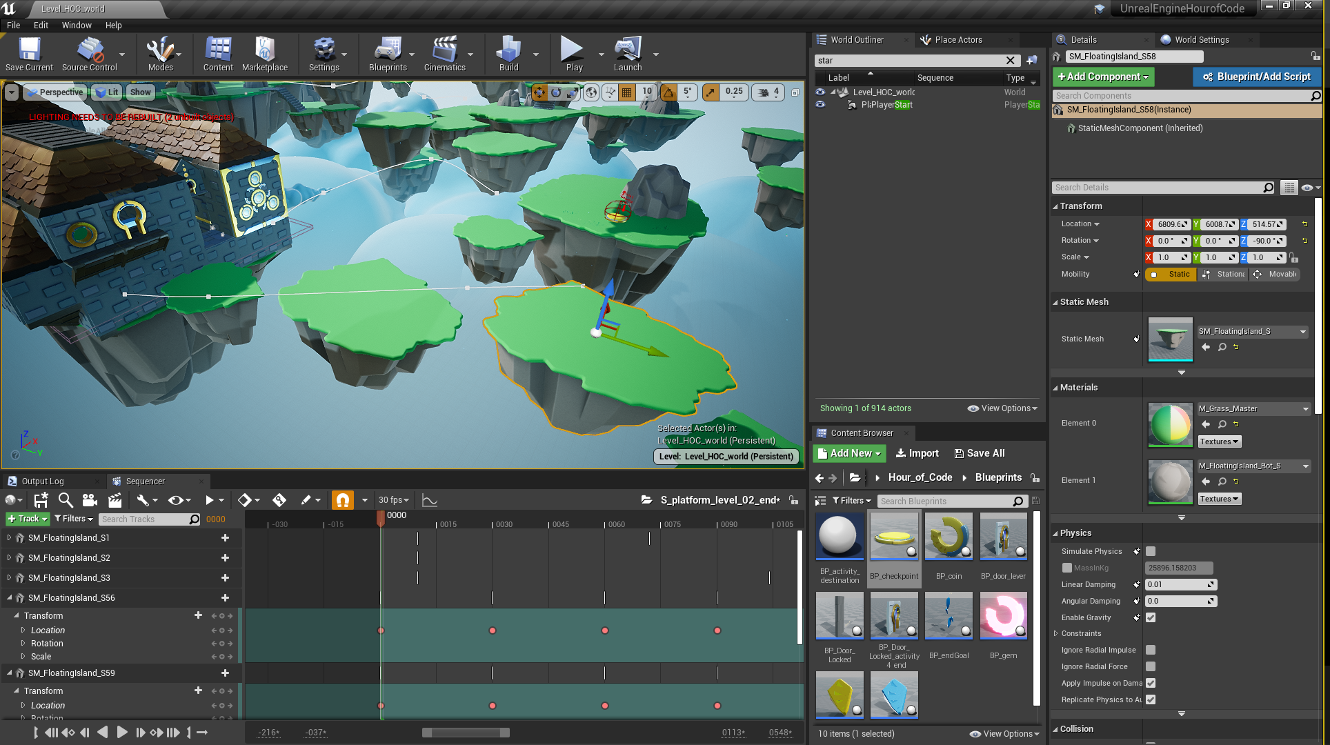
Level Sequencer

The Level Sequencer is its own window to help control the timeline of events and animations of objects throughout the level. In this tutorial, it was used to help control the infinite periodic movement of moving platforms.

Adding Actors to Level Sequencer:

Within the Sequencer window, go to “+ Track” and hover “Actor to Sequencer”. From here, a list of all possible actors comes up which can be added. You can also select an actor before this, and it will appear at the top of the list to make it easy to quickly add the currently selected actor to the Sequencer.

Widgets

Widgets are elements which make up the HUD or UI of the screen of the game.

Editing Text:

By default, text objects are not variables and are expected to be relatively static. If you want to have text that updates, like a collection counter of some kind, you need to make sure in the Widget Designer to check that a specific Text “Is Variable”, which can be found in the Details window. This appears to be similar to making a public text variable that is accessible in your blueprints.

Input Settings

You can get to the Input Settings through:

Edit -> Project Settings -> Engine-Input

Again, this is similar to the Input Settings in Unity where specific names or labels can be given to different actions which can then be tied to specific key bindings or joystick inputs. These names/labels can then be used in blueprints with nodes such as the InputAction node.

This approach is good to keep your inputs more organized. Your blueprints will be clearer since the name of the action will be there instead of arbitrary inputs like key “K”, and this makes it easier to modify inputs later if you want to change keybindings.

Blueprints Notes from Tutorial

This section covers many of the blueprints related notes that are given throughout the tutorial.

Within a Blue Print, in the Event Graph, some events can be added directly to components by selecting options presented in the Details tab for the currently selected component. For example, this tutorial starts with the checkpoint blue print and its sphere collider uses one of these events named “On Component Begin Overlap”. Selecting this immediately creates an event node in your event graph of that type referencing the currently selected component.

A lot of important information for your blue print can be found in the “My Blueprint” tab. This displays information such as the various functions and variables throughout the current blueprint.

Components can be dragged into the Event Graph from the Component tab to quickly use them as references for your blueprint.

Ctrl + W (In Blue Print editor): duplicates currently selected nodes/node system

Finding Variable References:

Select a variable under “My Blueprint” and right click and select “Find References”. This generates a list of references at the bottom of the editor which shows everywhere that variable is used. These can then be double-clikced to directly take the user to that specific reference.

Splitting Pins:

Some pins can be split into their more basic components in blueprints when necessary. This is done by right-clicking DIRECTLY on a pin, and selecting “Split Strcut Pin”. The example seen in this tutorial split a Transform pin so it then became 3 separate pins: position, rotation, and scale. These can then separately be connected into other pins.

IsValid Node:

Determines if input is valid or not, and performs functions based on the result. This can be used as a way to perform null reference checks to make sure to only do something as long as an input even exists or not.

PrintString Node:

Similar to the Debug.Log method in Unity, can be used to determine notes to be output as string data to check and debug blueprint maps.

DestroyActor Node:

Similar to the DestroyGameObject method within Unity, this is a quick and dirty way to remove something from existence in Unreal.

Auto Finding Proper Data from Variables Between Pins:

Sometimes you can drag a pin of one variable/class type to a pin of another variable type and it will add inbetween nodes to get a variable of the appropriate type for you that is contained within that class. For example, when connecting the actor pin of the OnComponentBeginOverlap node to a PrintString node’s string pin, it will add a GetDisplayName node in between to make sure it is passing the string data of the name of the object of interest into the PrintString node.

Casting Actors for More Detailed Variable Modification:

Many nodes work with Actors in blueprints, but often you need to adjust variables within deeper classes. When you need to start with a general node, but access a class inheriting from Actor, you can use a “Cast To …” node to get access to the proper tools. After casting to your designated class, it is then possible to modify the variables and values within that class.

The example from the tutorial is that the BP_jumpBoost wants access to the player character to modify their jump value. Since this is done when they collect the powerup, it starts with an OnComponentBeginOverlap node. This can return the other actor that collided with it, but they then need more detailed information to modify the jump value of the player character that collided with it than that it is just an Actor. This is done by a CastToEpicCharacter node that receives the OtherActor pin data from the OnComponentBeginOverlap node. This converts it to a more specific class, where the jump velocity can then be set as wanted.

This tutorial then suggests that using interfaces is another way to achieve a similar goal in these situations. They even prefer interfaces, but both appear to be valid approaches.

Adding Variables:

1) They can be added under the My Blueprint window within the blueprint

2) Select a variable pin, right-click, and select “Promote to Variable” (similarly to Houdini)

Variables in Details Window:

Displaying:

This can quickly be done by making the variable public. This can be done by clicking the eye icon next to the variable in your blueprint, making sure it displays an open eye (indicating the variable is now public).

Organizing:

Similar to having headers in Unity to group variables, Unreal does this with Categories. Just select the variable in your blueprint, and the Details window has a section named Category where a dropdown shows all the previously made Categories this variable can be placed in. If you want to make a new category to place the variable into, just type a new name there.

Controlling Variables:

Similar to Unity, public variables within the blueprints can also be given limits and controls for better usability in the Details window. For example, you can add a slider range to a variable which creates a slider in the Details window which can be dragged within the given minimum and maximum values.

Branch Node:

Foundational conditional statement for blueprints to do various events if true and/or false


Shortcut: Hold B + Left-Click (in Event Graph)

OnComponentBeginOverlap and OnComponentEndOverlap nodes:

These are similar to the OnCollision… Enter and Exit methods within Unity. They help determine what actions to take when something enters a collider, and what actions to take when leaving a collider.
Solely entering a collider is common when collecting objects, whereas entering and exiting a collider is common when certain actions by the player can only be performed when they are with a certain proximity to an object (such as being able to open a door), since you need to allow the object to receive input from the player while they are close, but then again stop receiving input once the player gets too far away.

Sequence Node:

Used to sequentially perform a number of methods in a designated order.

Making Your Own Blueprint; Common Components:

Static Mesh & Collider (of some type)

Creating Events and Functions:

Similar to the events and functions already present in Unreal, you can also create your own custom versions of these. These can then be called from other locations as long as they have a reference to the overall class, similar to calling methods of other classes in Unity or programming.

Fig. 1: Image from my Platform Setup with Sequencer in Tutorial

Summary

I think this was a very solid tutorial overall that made me feel much more confident in working with Unreal, especially when it comes to interacting with the blueprint system. I am starting to be able to draw parallels between Unreal’s blueprints and the code used to perform similar actions in Unity which is helping me start to understand adding functionality to objects in Unreal. One major difference is just that Unreal already offers so much to the designer immediately upon creating a new project that will just require experience to learn what is already there. For example, blueprints like those for the background game mode do a lot of work you might create for a game manager class or something similar in a Unity project.

Blueprints are also just so numerous that finding what you want as a beginner to the system can be too overwhelming to be practical. Simply having more experience helps understand the more commonly used ones however, like collider overlaps and branches, so I think just a few more tutorials will allow me to start building my own small projects.

via Blogger http://stevelilleyschool.blogspot.com/2021/04/unreal-tutorial-unreal-engine-426.html

Coding Adventure: Ray Marching by Sebastian Lague

April 12, 2021

Ray Marching

Unity


Title:
Coding Adventure: Ray Marching


By: Sebastian Lague


Youtube – Tutorial

Description:
Introduction to the concept of ray marching with some open available projects.


Overview

This video covers some of the basics of ray marching while also visualizing their approach and creating some interesting visual effects and renders with the math of signed distance along with ray marching logic. The major ray marching method they show is sphere tracing, which radiates circles/spheres out from a point until anything is collided with. Then, the point moves along the ray direction until it reaches the radius of that sphere projection and emits another sphere. This process is repeated until it radiates a very small threshold radius sphere, which is when a collision is determined.

The resulting project made is available, and I think it would be very useful and interesting to explore. The Youtube video description also holds many links to various sources used to create all the tools and effects in the video, which could also be beneficial for further research into these topics.

Fig. 1: Example of Raytracing Visual from Video (by Sebastian Lague)

via Blogger http://stevelilleyschool.blogspot.com/2021/04/coding-adventure-ray-marching-by.html

Linear Algebra and Vector Math – Basics and Dot Product – by Looking Glass Universe

April 8, 2021

Linear Algebra

Vectors and Dot Product


Title:
Vector addition and basis vectors | Linear algebra makes sense


Youtube – Link #1

Description:
Introduction to this series and the basics of linear algebra and vectors.


Title:
The meaning of the dot product | Linear algebra makes sense


Youtube – Link #2

Description:
Deep dive into the dot product and what it represents and how to determine it.


Overview

I wanted to brush up on my vector math fundamentals, particularly with my understanding of the dot product and its geometric implications as it is something that comes up often in my game development path. While I am able to understand it when reading it and coding it for various projects, I wanted to build a more solid foundational understanding so that I could apply it more appropriately on my own. This video series has been very nice for refreshing my learning on these topics, as well as actually providing me a new way of looking at vector math that I think will really further my understanding in the future.

Video #1 – Vector addition and basis vectors

This was the introductory video to the series, and starts with vector addition. They then move on to linear combinations as an extension of basic vector addition. Next they show for 2D vectors that as long as you have two independent vectors, you can calculate any other vector using those two in some linear combination. This then relates to how vectors are normally written out, but they are simply using linear combinations of the standard orthonormal basis of something like x and y, or x, y, and z in 3D space.

This means a vector is simply 2 or 3 vectors created with the unit vector in the x, y, or z direction multiplied by some scalar and then summed up to create the resulting vector. This was actually a new way for me to look at vectors, as this is more intuitive when you are looking to create a new vector set to base vectors off of different from the standard x, y, z, but I never really thought to also apply it in the standard case. The x, y, z, or even i, j, k, became some standardized to me that I generally ignored them, but I think looking at them in this way will help make much more of linear algebra more consistent in my thinking space.

They then continue on to explain spans, spaces, and the term basis a bit more. A set of vectors can be called a span. If that span is all independent vectors, this indicates it is the smallest amount of vectors which can fully describe a space, and this is known as a basis. The number of basis elements is fixed, and this is the dimension of the space (like 2D or 3D). And for a given basis, any vector can only uniquely be defined in one linear combination of the basis vectors.

Video #2 – The meaning of the dot product

Dot Product

A really simple way of describing the dot product is that it shows “how much one vector is pointing in the same direction of another vector”. If those two vectors are unit vectors, the dot product of two vectors pointing the same direction is 1, two vectors that are perpendicular would have a dot product of 0, and two vectors pointing directly opposite directions would have a dot product of -1. This is directly calculated as the cosine of the angle between the two vectors.

However, the dot product also factors in the magnitude of the two vectors. This is important because it makes the dot product a linear function. This also ends up being more useful when dealing with orthonormal basis vectors, which are unit vectors (vectors of length 1) that define the basis of a space and are all orthogonal to each other.

They cover a question where a vector u is given in the space of the orthonormal vectors v1 (horizontal) and v2 (vertical) and ask to show what the x value of the u vector is (which is the scalar component of the v1 vector part of the linear combination making up the vector u) with the dot product and vectors u and v1. Since v1 is a unit vector, this can be done directly by just the dot product (u . v1). They then show that similarly the y component would just be the dot product (u . v2). They explain this shows the ease of use of using the dot product along with an orthonormal basis, as it directly shows the amount of each basis vector used in the linear combination to create any vector. This can also be explained as “how much of u is pointing in each of the basis directions”.

Since the dot product is linear, performing the dot product function on two vectors is the same whether done directly with those two vectors, or even if you break up one of the vectors before hand into a linear combination of other vectors and distribute it.


Example:

a . b = (x*v1 + y*v2) . b = x*v1 . b + y*v2 . b

Projecting a Vector onto Another Vector

They then cover the example I was very interested in, which is what is the length of the vector resulting in projecting vector A onto vector B in a general sense. The length, or magnitude, of this vector is the dot product divided by the magnitude of vector B. This is similar to the logic in the earlier example showing how vectors project onto an orthonormal basis, but since they had magnitudes of 1 they were effectively canceled out originally.

This then helped me understand to further this information to actually generate the vector which is the projection of vector A onto vector B, you then have to take that one step more by multiplying that result (which is a scalar) with the unit vector of B to get a vector result that factors in the proper direction. This final result ends up being the dot product of A and B, divided by the magnitude of B, then multiplied by the unit vector of B.


Example:

Projection vector C

C = (A . B) * ^B / ||B|| = (A . B) * B / ||B||^2

Dot Product Equations

They have generally stuck with the dot product equation which is:

a . b = ||a|| ||b|| cos (theta)


They finally show the other equation, which is:

a . b = a1b1 + a2b2 + a3b3 + …

But they explain this is a special case which is only true sometimes. It requires that the basis you are using is orthonormal. So this will generally be true in many standard cases, but it is important to note that it does require conditions to be met. This is because the orthonormal basis causes many of the terms to cancel out, giving this clean result.

via Blogger http://stevelilleyschool.blogspot.com/2021/04/linear-algebra-and-vector-math-basics.html

2014 GDC Talk – 50 Game Camera Mistakes

April 6, 2021

GDC 2014 Talk

Camera Controller


Title:
GDC 2014 Talk – 50 Game Camera Mistakes


Youtube – Link

Description:
A talk on common issues with camera controllers game developers make and how to avoid them.


Overview

As I was fixing some issues I had with my Unity camera for my architecture project, I came across this talk and thought it would be useful moving forward to understand camera controllers in games in general. It’s a bit older, but it should still be very useful for getting some tips for establishing a base understanding of some issues you may run into starting a camera controller.

via Blogger http://stevelilleyschool.blogspot.com/2021/04/2014-gdc-talk-50-game-camera-mistakes.html

Basics of Bits and Bytes with C++: Operands and Manipulation

March 26, 2021

Manipulating Bits and Bytes

C++


Title:
Wikipedia – Bitwise Operation


Wikipedia – Bitwise Operation

Description:
Wikipedia’s page on bitwise operations.


Title:
Bitwise Operators in C/C++


GeeksforGeeks – Bitwise Operators

Description:
The basics of bitwise operators and using them in C and C++ with some guidance on more involved usage.


Title:
sizeof operator


cppreference – sizeof operator

Description:
Definition of the sizeof operator used in C++ to find the size of an something in bytes.


Title:
Bit Manipulation

By:
Make School


Youtube – Tutorial #1

Description:
Basic introduction to bit operators as well as how to use them together for simple manipulation.


Summary

These are several of the more encompassing sources I came across recently on the basics of working with bits and bytes, especially in C++. More directy memory management and bit manipulation is not something I come across often using C# in Unity, but it still seems good to understand as it does come up every now and then. Unity uses bit maps for instance with their layer masks, which reading these sources greatly helped me understand better. I am also starting to do more work in Unreal, which uses C++ as its primary language, where I feel like this type of work is done more often.

via Blogger http://stevelilleyschool.blogspot.com/2021/03/basics-of-bits-and-bytes-with-c.html

Architecture AI Pathing Project: Fixing Highlight Selection Bugs

March 22, 2021

Highlight Selection

Architecture AI Project


Overview

I was having a bug come up with our selection highlight effect where sometimes when moving around quickly, several objects could be highlighted at the same time. This is not intended, as there should ever only be a single object highlighted at once, and it should be the object the user is currently hovering over with the mouse.

Bugfix

Assessing Bug Case

Since it happened generally with moving around quickly in most cases, it was difficult to nail down the direct cause at first. After testing a while though, it was noticeable that the bug seemed to occur more often when running over an object that was non-selectable, onto a selectable object. Further testing showed this was the case when directly moving from a non-selectable to a selectable object right afterward. This helped isolate where the problem may be.

Solution

It turns out in my highlight selection SelectionManager class, I was only unhighlighting an object if the ray did not hit anything or it did both: 1) hit an object and 2) that object had a Selectable component. I was however not unhighlighting an object if the ray: 1) hit an object and 2) that object did NOT have a Selectable component. This logic matched up with the bug cases I was seeing, so this was the area I focused on fixing.

It turns out that was where the error was coming in. By adding an additional catch for this case to also unhighlight an object when moving directly from a selectable object to a non-selectable and back to a selectable object again, the bug was fixed.

Architecture AI Project: Fixing Selection Highlight Bug from Steve Lilley on Vimeo.

Summary

This was a case of just making sure you are properly exiting states of your system given all cases where you want to exit. This could probably use a very small and simple state machine setup, but it seemed like overkill for this part of the project. It may be worth moving towards that type of solution if it gets any more complex however.

via Blogger http://stevelilleyschool.blogspot.com/2021/03/architecture-ai-pathing-project-fixing_22.html

Intro to Unreal: Basics and Intro to Blue Prints

March 17, 2021

Intro and Blue Prints

Unreal


Title:
Unreal Engine 4 Complete Beginners Guide [UE4 Basics Ep. 1]

By:
Smart Poly


Youtube – Tutorial

Description:
A quick introduction to using the Unreal engine and just getting acquainted with the main editor window.


Title:
Unreal Engine 4 – Blueprint Basics [UE4 Basics Ep. 2]

By:
Smart Poly


Youtube – Tutorial

Description:
Quick introduction to using Unreal’s blueprints.


Title:
Unreal Gameplay Framework

By:
Unreal


Unreal – Link

Description:
Unreal Gameplay Framework, the official Unreal documentation.


Learning the Basics

It has been a while since I have used Unreal in any significant capacity, so I am going back to the basics to try and make sure I have all the fundamentals covered.

Tutorial #1

Moving/Positioning Objects

By default, Unreal has all the transformation functions snap. So moving an object, rotating it, and scaling it all occur in steps as opposed to smooth transforms. This can easily be changed in the top right of the viewport at any time.

Extra Camera Controls

F: focuses on object (like Unity)

Shift + move an object: Camera follows the moving object

You can directly change the camera speed in the top right of the viewport.

Adding Content Pack Later

If you find that you want to add the starter content to a project later than the start, this can easily be done through “Content” in the “Content Browser” window, then “Add New”, and choosing “Add Feature or Content Pack”. The starter content options will be one of the first to show up by default under the “Content Packs”.

Lighting Basics

“LIGHTING NEEDS REBUILT” Error Message

The static meshes want the lighting to be rebuilt when added so they are accounted for. Fixed with:

Go to: Build -> Build Lighting Only

Light Mobility Options

Lights by default have 3 mobility options: Static, Station, Movable

  • Static: can’t be changed in game; fully baked lighting
  • Station (Default): only shadowing and bounced lighting from static objects baked from Lightmass; all other lighting dynamic; movable objects have dynamic shadows
  • Movable: fully dynamic lighting, but slowest rendering speed

Tutorial #2

General Structure of Blue Prints

Components:

area where different components can be added

what allows you to place objects into the viewport of the blue print

this is where colliders are shaped to the proper size/shape


Details:

all the different details for this particular blue print


Event Graph:

this is the tab where visual scripting is majorly done


Function:

effectively contained event graphs with more specialized functionality


Variables:

representation of fields as you’d expect

Events

These are events which call the given functions when something in particular occurs. These functions are created within the blue print Event Graph.

Actions (Examples)

On Component Begin Overlap: occurs when something initially enters a collider
– Similar to Unity’s OnTriggerEnter

On Component End Overlap: occurs when something initially leaves a collider
– similar to Unity’s OnTriggerExit

E: occurs when the “E” key is pressed

Action: Timeline

Timeline:

allows you to visually create a graph of how a variable changes over a particular set of time

By default, the x-axis is the time and the y-axis is the variable value.
Points can be added as wanted to act as key frames for the variable.
Also allows for easy modifications to the interpolation between points, such as changing it from a line to a cubic interpolation by selecting multiple points.

Make sure to pay attention to the time Length set in the time line. Even if you didn’t put points somewhere in particular, if that is way longer than where your points are, you can get strange results since it will perform the action over the entire length of time.

Debugging Blue Prints

If you select Play from within the blue print, you can get a separate play window while leaving the blue print window visible. This can be helpful for example with the Event Graph, as you can actually see when different events occur according to the system and when inputs are read. This also shows the variables changing in some nodes, such as Timeline.

Classes (as covered by the Gameplay Framework Quick Reference)

Agents

Pawn

Pawns are Actors which can be possessed by a controller to receive input to perform actions.

Character

Characters are just more humanoid Pawns. They come with a few more common components, such as a CapsuleComponent for collision and a CharacterMovementComponent by default.

Controllers/Input

Controllers are Actors which direct Pawns. These are generally AIController (for NPC Pawns) and PlayerController (for player controlled Pawns). A Controller can “possess” a Pawn to control it.

PlayerController

the interface between a Pawn and the human player

AIController

simulated AI control of a Pawn

Display Information

HUD

Focused on the 2D UI on-screen display

Camera

The “eye” of a player. Each PlayerController typically has one.

Game Rules

GameMode

This defines the game, including things such as game rules and win conditions. It only exists on the server. It typically should not have much data that changes during play, and definitely should not have transient data the client needs to know about.

GameState

Contains the state of the game.
Some examples include: list of connected players, score, where pieces in a chess game are.
This exists on the server and all clients replicate this data to keep machines up to date with the current state.

PlayerState

This is the state of a participant in the game (which can be a player or a bot simulating a player). However, an NPC AI that exists as part of the game would NOT have a PlayerState.
Some examples include: player name, score, in-match level for a MOBA, if player has flag in a CTF game.
PlayerStates for all players exist on all machines (unlike PlayerControllers) and can replicate freely to keep machines in sync.

via Blogger http://stevelilleyschool.blogspot.com/2021/03/intro-to-unreal-basics-and-intro-to.html

Intro to Unreal: Basics Tutorial Compilation

March 16, 2021

Intro and Basics

Unreal


Title:
Unreal Engine 4 Complete Beginners Guide [UE4 Basics Ep. 1]

By:
Smart Poly


Youtube – Tutorial

Description:
A quick introduction to using the Unreal engine and just getting acquainted with the main editor window.


Title:
Unreal Engine 4 – Blueprint Basics [UE4 Basics Ep. 2]

By:
Smart Poly


Youtube – Tutorial

Description:
Quick introduction to using Unreal’s blueprints.


Title:
Unreal Engine 4 Beginner Tutorial: Getting Started

By:
DevAddict


Youtube – Tutorial

Description:
A more in depth intro to getting through the Unreal editor and starting to apply it to some general case uses.


Title:
Unreal Engine Beginner Tutorial: Building Your First Game

By:
Devslopes


Youtube – Tutorial

Description:
A good introduction focusing on building more of your own assets instead of using the Unreal given assets.


Title:
Unreal Engine 4.26 Beginner’s Tutorial: Make a Platformer Game

By:
DevAddict


Youtube – Tutorial

Description:
A large tutorial focusing on fleshing out the functionality of a given project and assets in Unreal.

Summary

This is a quick list of some Unreal tutorials just to get familiar with the engine. I listed them in order of a progression that I believe makes sense, where the first couple simply introduce the main Unreal editor and some of the tools it gives you, and the later tutorials start to implement those individual components to varying degrees. Some of these focus on using blue prints, while some focus on applying parameters to assets just through the Unreal editor directly. Finally, some of the tutorials near the end beging to show these tools making more complete systems and projects.

via Blogger http://stevelilleyschool.blogspot.com/2021/03/intro-to-unreal-basics-tutorial.html

Architecture AI Pathing Project: Cleaning Build UI

March 15, 2021

Working with UI

Architecture AI Project


Working with UI

Since UI looked organized into 4 major groups vertically, I used a Vertical Layout Group for the overall control. I then filled this with 4 empty UI objects, one for each major UI group.

Vertical Layout Group

  • Anchor Preset: stretch/left (anchors to the left, but expands for full vertical screen space)
  • Pivot: (0, 0.5) (Moves pivot point to the far left, so width controls how much it expands out from edge, and Pos X can just remain 0)
  • Child Force Expand: Width (Helps expand everything to fit the full width)
  • Child Force Expand: Height (May not be needed)
  • Control Child Size: Width (May not be needed)
  • Padding: Left, Top, Bottom (Keep everything slightly away from edge)

Controlling the anchors and pivot is extremely important. After setting up the vertical layout group, a lot of the individual control is necessary for the horizontal organization. The anchors, the x position in particular, can be used to help stretch the UI objects to fit whatever is dictated by the overall layout group container.

Using Anchors

For example, many objects are side by side and want to fit half of the given width. To do this, the left object uses anchor X values of min = 0.0 and max = 0.5. The right object uses X values of min = 0.5 and max = 1.0. The values are percentage based, so this allocates the first half of the given space to the first object and the second half to the other.

Using Pivots

The pivot then ties in as this is the base point, or handle of the UI object, so this is the point that all the positioning is relative to. So many of the objects start with a pivot at (0.5, 0.5), which is in the center of the object. This requires annoying extra positioning values, normally half of the width of the object, to fit properly. By moving the pivots though, they become much easier to position.

Again, looking at the UI examples that have 2 objects split the space horizontally, the pivots are used somewhat similarly to the anchors. The left object has its pivot set to (0, 0.5), so the X is set to 0.0. The right object has its pivot set to (1.0, 0.5), so the X is set to 1.0. These are again percentage based, so the (0, 0.5) pivot moves the handle to the extreme left of the object, and the (1.0, 0.5) moves the pivot to the extreme right. This way, the “X position” (now named Left and Right) can just be set to 0. This is conjunction with the edited anchor points will position the object perfectly to fill half the space horizontally.

These uses of UI anchor and pivots can be seen in the following figure in the bottom two groups of UI elements as I worked through applying them (the section with the “Run Sim” button and the section with the “Output .csv” button). The upper sections had not been modified yet.


Fig. 1: Example of These UI Modifications in During Work in Progress (Only Lower 2 Sections)

Summary

I learned a lot about the workings of UI elements in Unity by getting this setup much more organized. The anchors help locate the extents of the positions of a UI element, where as the pivot is simply the base point all the positioning and scaling originates. I also found that changing the anchor presets just has a set value for this different options (which completely makes sense once you look at it). For instance, stretch just sets the anchors to 0.0 and 1.0 to force it to fit the area it is parented by (or the entire screen).

via Blogger http://stevelilleyschool.blogspot.com/2021/03/architecture-ai-pathing-project.html

Architecture AI Pathing Project: Fixing Weird Build Bugs

March 11, 2021

Build Issues

Architecture AI Project


Overview

After working on the project with a focus on using it in Editor for a while, we finally decided to try and see if we could build the project and work with it from there. Initially it did not provide anything useable. It would build, but nothing could be done. After a while, I isolated that the colliders were giving trouble so I manually added them for a time and that helped set up the base node grid. The file reader however was unable to provide data to the node grid, so only one aspect of applying data to the pathing node grid worked.

These issues made the build fairly unuseable, but provided some aspects to approach modifying in order to fix the build. After some work focusing on the issue with applying colliders and reading/writing files, I was able to get the builds into a decently workable spot with hope to get the full project useable in a build soon!

Unable to Apply Colliders with Script: Working with Mesh Colliders at Run Time

This first issue right off the start of opening the build was that my script for applying mesh colliders to all aspects of the model of interest was not working. This made sense as a cause for the node grid not existing as raycasts need something to hit to send data to the node grid. Further testing with simply dropping a ball in the builds showed it passed right through, clearly indicating no colliders were added.

I used a band aid fix temporarily by manually adding all the colliders before building just to see how much this fixed. This allowed the basic node grids to work properly again (the walkable and influence based checks). The daylighting (data from the file reader) was not working still however, which showed another issue, but it was a step in the right direction.

Solution

With some digging, I found that imported meshes in Unity have a “Read/Write Enabled” check that appears to initially be set to false on import. While this does not seem to have an effect when working in the editor, even in the game scene, this does seem to apply in a build. So without this checked, the meshes apparently lose some editing capabilities at run time, which prevented the colliders from being added by script. Upon checking this, adding the colliders worked as intended.

File Reader Not Working: Differences Between Reading and Writing Text Files in Unity, and the Difficulties of Writing

While this got the build up and working at least, we were still missing a lot of options with the node grid not being able to read in data from the File Reader. Initially I thought that maybe the files being read were just non-existent or packaged incorrectly so I checked that first. I was loading the files in through Unity’s Resources.Load() with the files in the Resources folder, so I thought they were safe, but I still needed to check. To do so I just added a displayed UI text that read out the name of the file loaded if found, and read out an error if not found. This continuously provided the name of the file, indicating it was being found and that may not be the problem.

Difference Between “Build” and “Build and Run” in Unity

I was doing all my testing by building the project, and then finding the .exe and running it myself. Eventually I tried “Build and Run” just to test a bit faster, and to my surprised, the project totally worked! The File Reader was now working as intended and the extra pathing type was being read in properly and applied to the underlying node grid! But this was not a true solution.

To double check, I closed the application and tried to open it again directly from the .exe. Once I did, I found that again, the project was NOT applying the data properly and the file reader was NOT working as intended. This is important to note as “Build and Run” may give false positives for your builds working, when they actually don’t when run properly.

I found an attempt at an explanation here when looking for what caused this, as I hoped it would also help me find a solution:


Unity Forums – Differences between Build – Build&Run?


One user suggests some assets read from the Assets folder within Unity’s editor may still be in memory when doing “Build and Run”, which is not the case when simply doing a build. Further research would be needed though to clarify what causes this issue.

Solution

This did not directly lead me to my solution, but it did get me looking at Unity’s development builds and the player.log to try and find what issues were being created during the running of the build. This showed me that one part of the system was having trouble writing out my debug logs that were still carrying over into the build.

Since these were not important when running the build, I just tested commenting them out. This actually fixed the process and the File Reader was able to progress as expected! This read the file in at run time, and applied the extra architectural data to the pathing node grid as intended!

Reading vs. Writing Files through Unity

This showed me some differences in reading and writing files through Unity, and how writing requires a bit more work in many cases. Unity’s build in Resources.Load() works plenty fine as a quick and dirty way to read files in, even in the building process as I have seen. Writing out files however requires much more finesses, especially if you are doing something with direct path names.

Writing out files pretty much requires .NET methods as opposed to built in Unity methods, and as such might not work as quickly and cleanly as you hope without some work. When done improperly, as I had setup initially, it directly causes errors and stops in your application when you finally build it as the references will be different from when they were running in the Unity editor. This is something I will need to explore more as we do have another aspect of the project that does need to write out files.

Summary

If you want to modify meshes in your builds and you run into issues, just make sure to check if the mesh has “Read/Write Enabled” checked. Reading files with Unity works consistently when using a Resources.Load() approach, but writing out files is much trickier. Finally, use the dev build and player.log file when building a project to help with debugging at that stage.

via Blogger http://stevelilleyschool.blogspot.com/2021/03/architecture-ai-pathing-project-fixing.html